[0013]In view of the foregoing, various embodiments of the present invention advantageously provide an apparatus and methods for economically and efficiently burning viscous biofuels in a combustion chamber to produce an exhaust which can be utilized as an
energy source. Various embodiments of the present invention also advantageously provide an apparatus and methods which include a vortex combustion chamber configured to provide flameless combustion to thereby decrease
nitric oxide emissions and increase energy efficiency. Various embodiments of the present invention provide an apparatus and methods which improve upon the Jirnov vortex combustion chamber and precombustion chamber described in U.S. Pat. No. 5,839,270 by Jirnov et al., titled “Sliding-Blade Rotary Air-
Heat Engine with Isothermal Compression of Air,” to more efficiently accommodate use of the more viscous fuels, such as
glycerol.
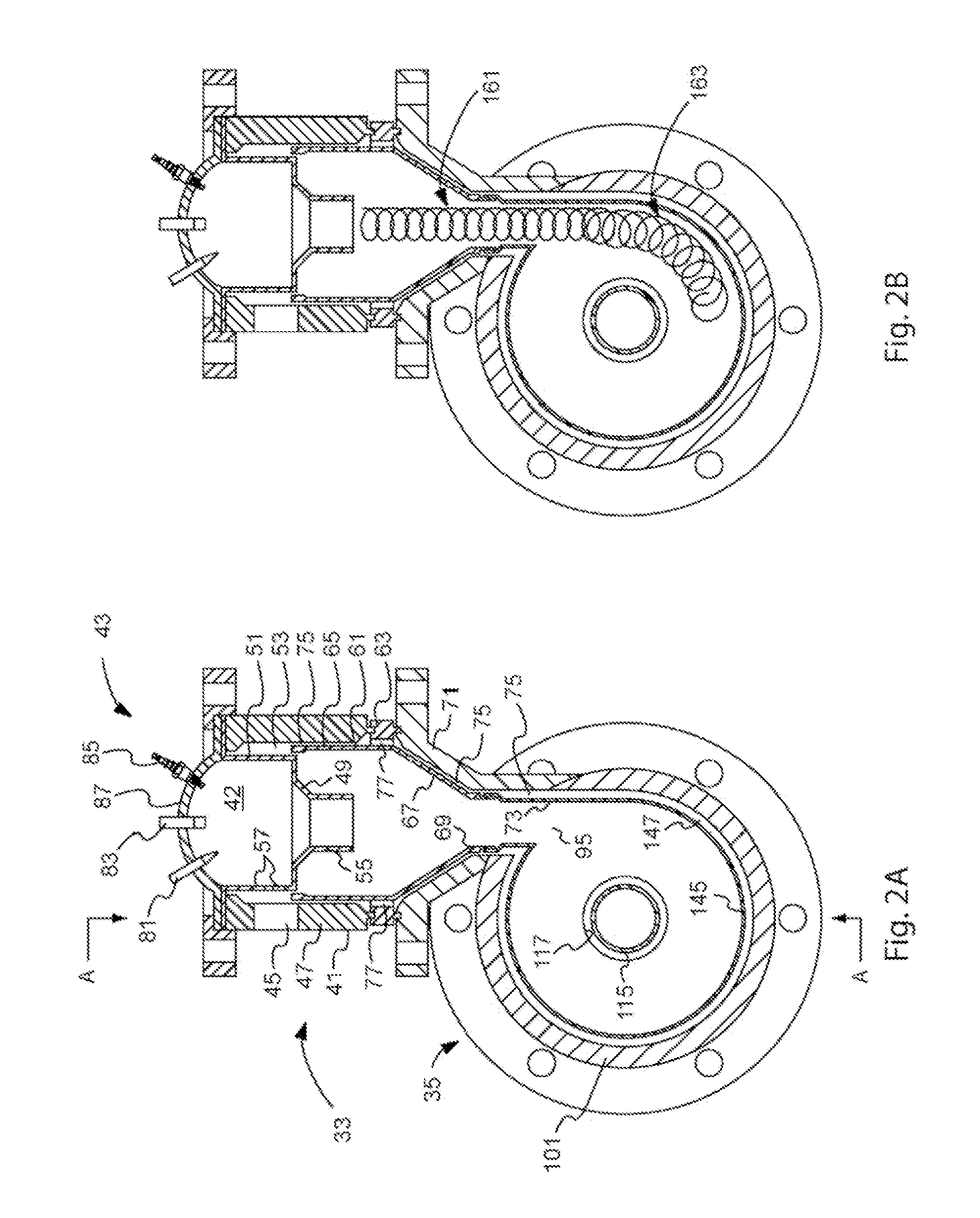
[0020]Various embodiments of the present invention also provide methods of providing flameless combustion of a viscous fuel. According to an embodiment of the present invention, such a method can include the steps of inducing a first stage vortex in a primary fuel-air mixture within a main body of a precombustion chamber of a flameless
combustor, receiving within a main body of a main combustion chamber of the flameless combustor the primary fuel-air mixture having a first stage vortex induced state, and inducing a second stage vortex in the received primary fuel-air mixture to form a complex vortex pattern to thereby enhance flameless oxidation of the primary fuel within the main body of the main combustion chamber. According to a preferred configuration, the step of inducing can include expelling the primary fuel-air mixture tangentially into the main combustion chamber cavity through a precombustion chamber exhaust outlet. According to this configuration, the
diameter of the first stage vortex is substantially smaller than a
diameter of the second stage vortex formed within the main combustion chamber.
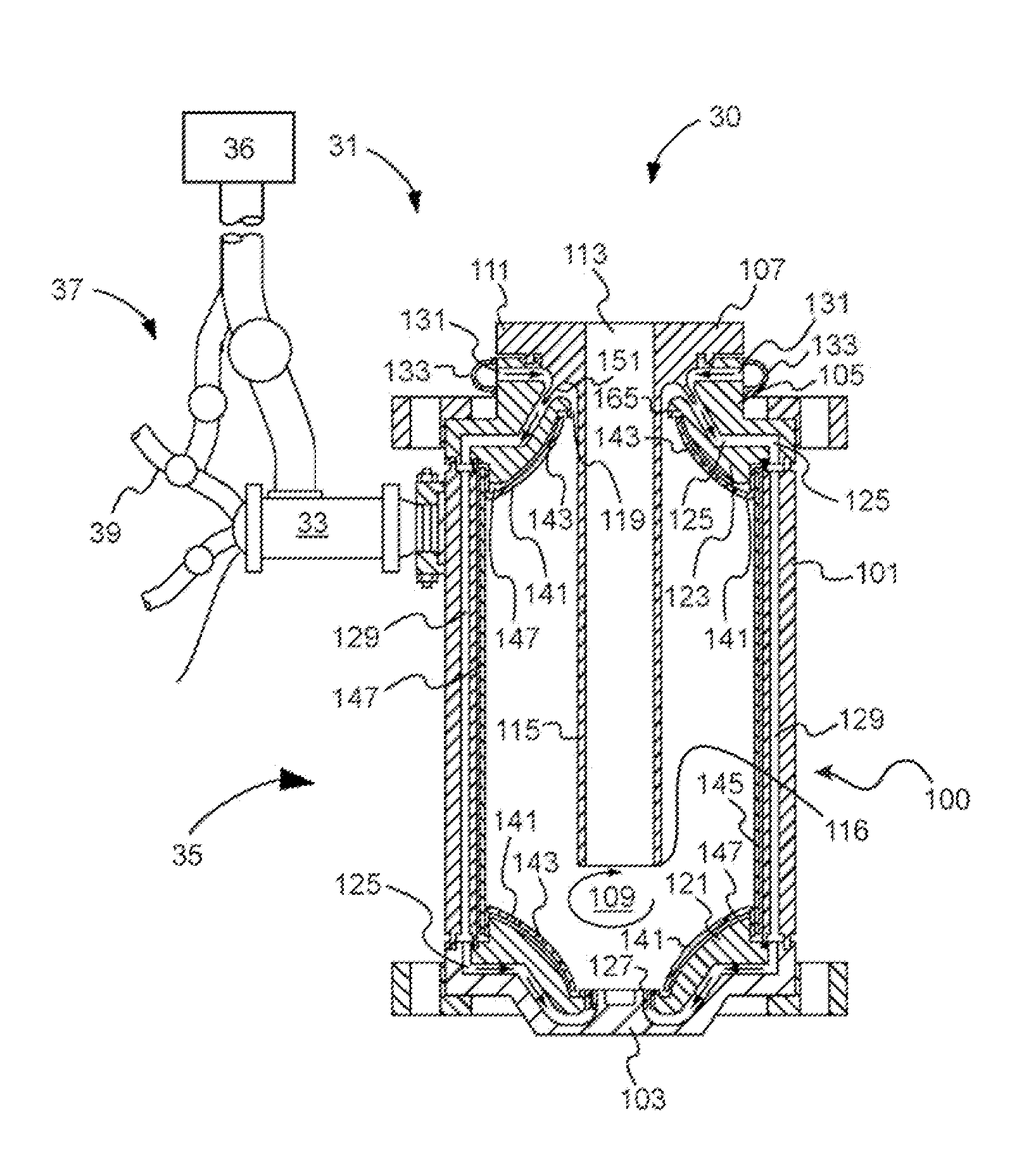
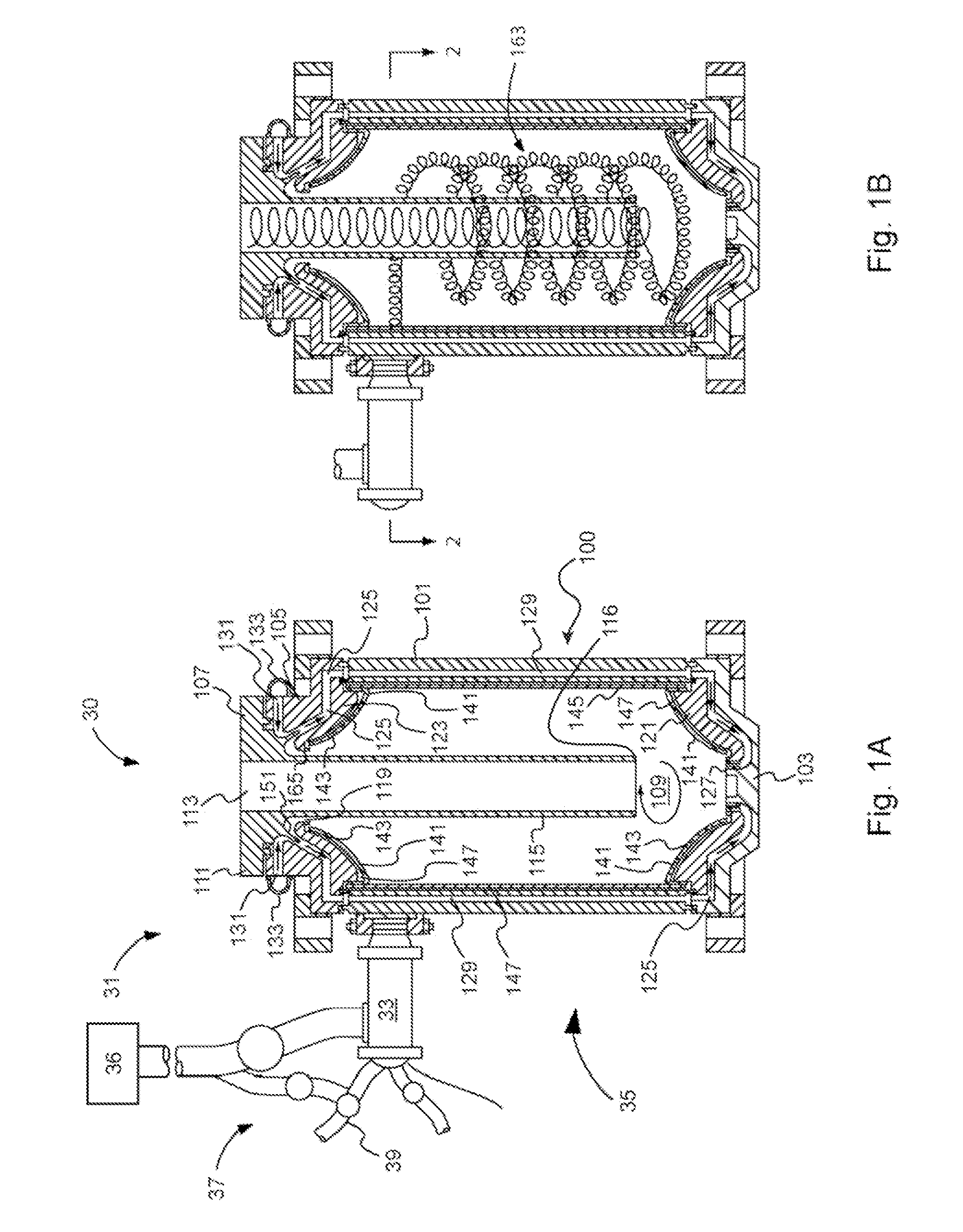
[0022]According to another embodiment of the present invention, a method of providing flameless combustion of a viscous fuel can include the steps of providing a main vortex combustion chamber of a flameless combustor having a main body substantially enclosing a main combustion chamber cavity having an
axial length approximately equal to or greater than an inner
diameter of the main combustion chamber cavity, and inducing a vortex within the main combustion chamber cavity to enhance flameless oxidation of a primary fuel. The method can also include the step of providing a combustion exhaust conduit within and axially coincident with the main combustion chamber cavity. The combustion exhaust conduit can have an inlet positioned at a location between an axial position distally forward of an axial midpoint position of the elongate main body of the main combustion chamber housing and an axial position within the main combustion chamber cavity adjacent the distal end portion of the main combustion chamber housing. The axial spacing of the distal end portion of the combustion exhaust conduit from an inner surface of the distal end portion of the main combustion chamber housing can further have a value approximately equal to or greater than that of at least one exhaust conduit main body inner diameter.
[0024]Various embodiments of the present invention also provide a precombustion chamber, and a vortex combustion chamber which is an improvement over the Jirnov vortex combustion chamber and precombustion chamber. Various embodiments of the present invention provide, for example, a vortex combustor including a main combustion chamber connected or otherwise interfaced with a precombustion chamber, which successfully solves problems associated with operating on highly viscous fuels with a high completeness of combustion over the wide range of the coefficient of air redundance and produces a substantial reduction in
toxicity of exhaust gases. Various embodiments of the present invention provide high thermal and
volumetric efficiency, may employ a variety of types of viscous and non-viscous combustible
hydrocarbon fuels, have reduced quantities of environmentally damaging emissions, and have a simplified combustor design and ease of fabricating, which is economical to manufacture in
mass production and is inexpensive to operate, service, and repair.
[0025]Various embodiments of the present invention provide a vortex chamber positioned at the tube inlet and provide feedback loops positioned along the length of the
heat transfer section, which enable the resulting fuel combustion efficiency to be increased by inducing a swirl flow and intensive recirculation of fluid along the length of the
heat transfer section. Such improved
fuel efficiency can advantageously reduce environmentally damaging emissions. Further, such apparatus may be used in converting
thermal energy into
electric power, can be used in generating steam, and / or can be utilized as part of a transportation engine with high
thermal efficiency.

