

Thermoelectric conversion material and thermoelectric conversion module
a technology of thermoelectric conversion module and thermoelectric conversion material, which is applied in the direction of thermoelectric device junction materials, basic electric elements, thermoelectric devices, etc., can solve the problems of poor electrode material performance, deterioration of thermoelectric properties, and breaking at the joining portions, so as to achieve excellent junctions, excellent thermoelectric performance, and effective prevention of diffusion of thermoelectric conversion material and electrode constituents
- Summary
- Abstract
- Description
- Claims
- Application Information
AI Technical Summary
Benefits of technology
Problems solved by technology
Method used
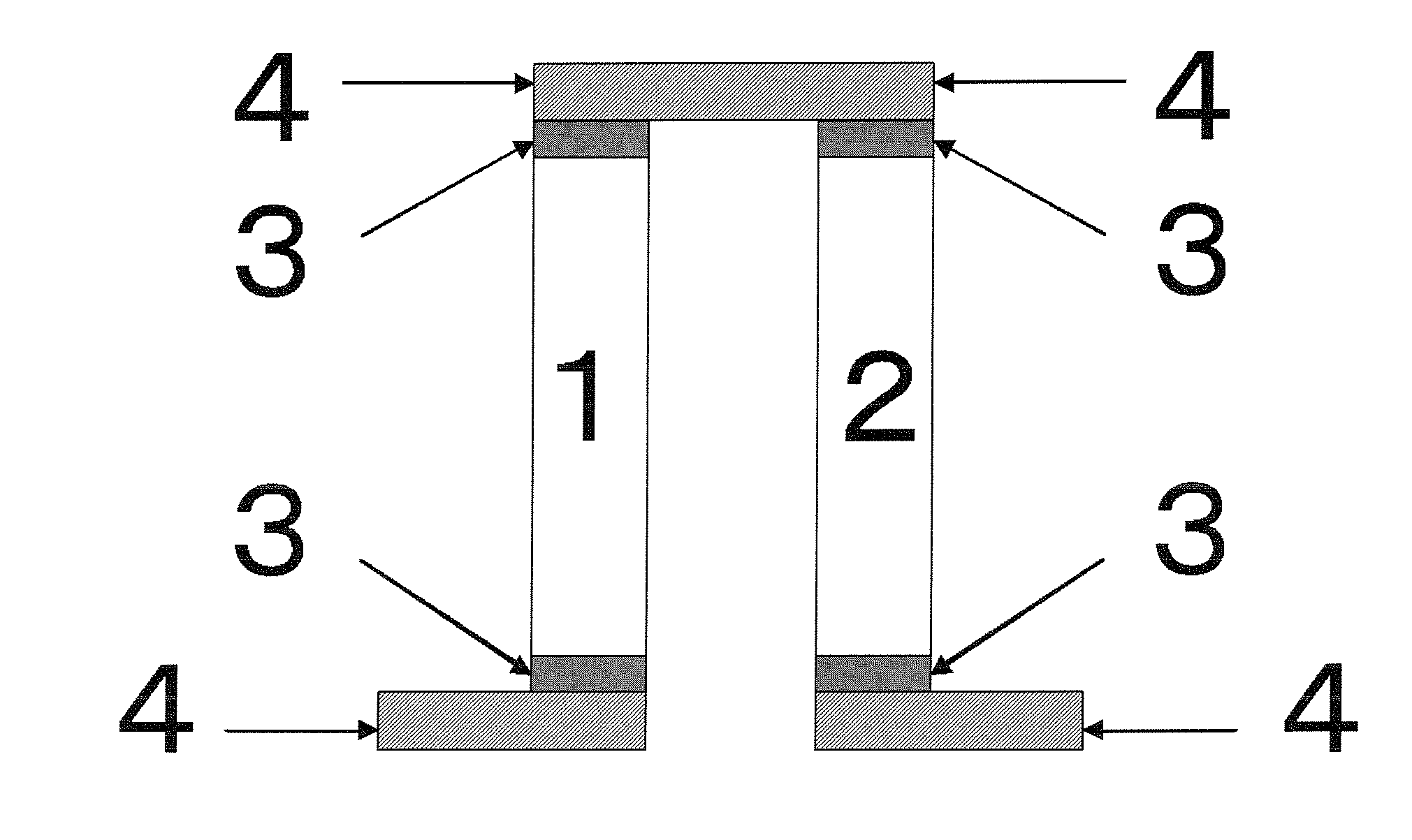
Image

Examples
examples
[0105]Thermoelectric conversion materials and thermoelectric conversion modules according to the present invention will be described below by way of examples. Thermoelectric conversion materials and thermoelectric conversion modules according to the present invention are not limited to the following descriptions, and various changes and modifications may be made to them without departing from the scope of the invention.
[Thermoelectric Conversion Materials]
(Evaluation of Thermoelectric Properties)
[0106]Thermoelectric conversion materials were evaluated as follows.
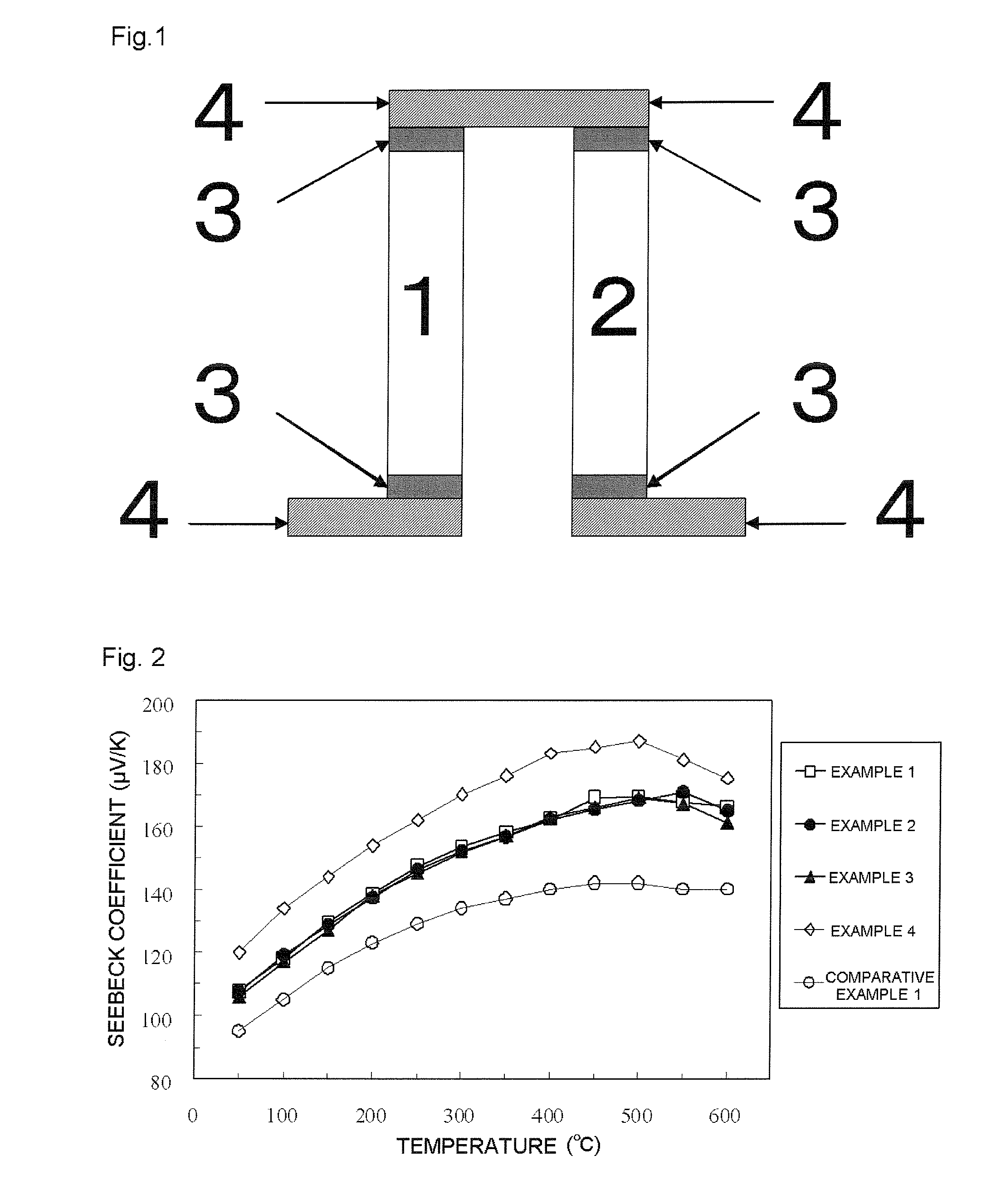
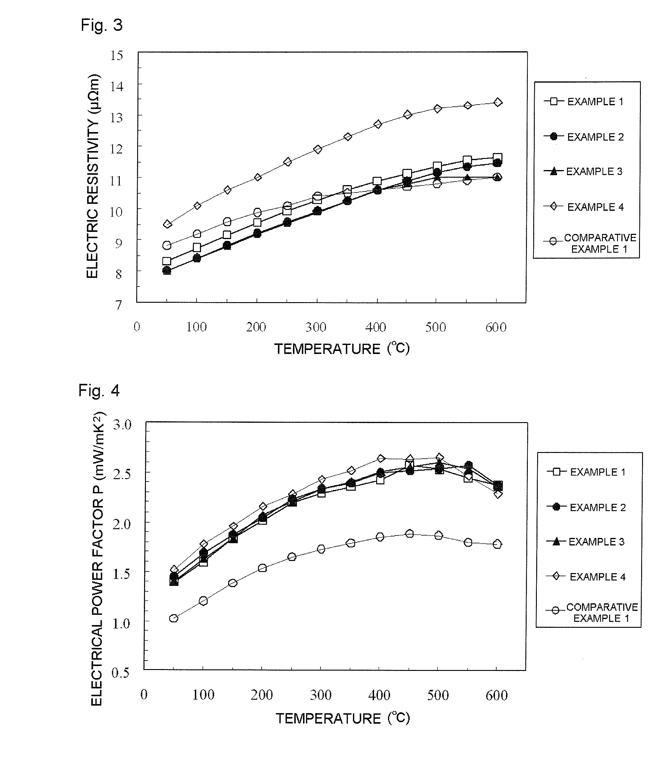
[0107]With the use of thermoelectric property evaluation instruments (thermoelectric property evaluation system ZEM-2 and laser flash method thermal constant measuring system TC-7000H, manufactured by ULVAC-RIKO, Inc.), the Seebeck coefficient S, the electric resistivity ρ, and the thermal conductivity κ of each thermoelectric conversion material were measured at temperatures ranging from room temperature to 600° C., and the...
examples 1 to 4
[0108]In Examples 1 to 4, the following p-type thermoelectric conversion materials were used.
[0109]Example 1 p-type La0.7Ba0.07Ga0.1Co1Fe3Sb12
[0110]Example 2 p-type La0.7Ba0.07Ti0.1Co1Fe3Sb12
[0111]Example 3 p-type La0.7Ba0.01Ga0.1Ti0.1Co1Fe3Sb12
[0112]Example 4 p-type La0.7Ba0.01Ga0.1Ti0.1Co1.2Fe2.8Sb12
[0113]The method for synthesizing the p-type thermoelectric conversion materials of Examples 1 to 4 is described below.
[0114]Pure metals La, Ba, Ga, Ti, Co, Fe, and Sb in predetermined proportions were put into a crucible made of carbon, and were heated to 1200° C. and melted by heating in an inert gas atmosphere with an electric furnace. After being maintained for 5 hours, they were water quenched. The water quenched materials were then heated to 700° C. After being maintained for 24 hours, they were cooled to room temperature to obtain a desired ingot. The ingot material was pulverized, and the obtained powders were put into a carbon die. They were heated to a temperature of 500 ...
examples 5 to 10
[0123]In Examples 5 to 10, the following n-type thermoelectric conversion materials were used.
[0124]Example 5 n-type Yb0.3Ca0.1Al0.1Co3.75Fe0.25Sb12
[0125]Example 6 n-type Yb0.3Ca0.1Ga0.1Co3.75Fe0.25Sb12
[0126]Example 7 n-type Yb0.3Ca0.1In0.1Co3.75Fe0.25Sb12
[0127]Example 8 n-type Yb0.3Ca0.1Al0.1Ga0.1Co3.75Fe0.25Sb12
[0128]Example 9 n-type Yb0.3Ca0.1Al0.1Ga0.1In0.1Co3.75Fe0.25Sb12
[0129]Example 10 n-type Yb0.3Ca0.1Al0.1Ga0.1In0.3Co3.75Fe0.25Sb12
[0130]The method for synthesizing the n-type thermoelectric conversion materials of Examples 5 to 10 is described below.
[0131]Pure metals Yb, Ca, Al, Ga, In, Co, Fe, and Sb in predetermined proportions were put into a crucible made of carbon, and were heated to 1200° C. and melted by heating in an inert gas atmosphere with an electric furnace. After being maintained for 5 hours, they were maintained at 900° C. for 6 hours, 800° C. for 12 hours, 700° C. for 24 hours, and further, 600° C. for 12 hours. They were then cooled to room temperature...
PUM
| Property | Measurement | Unit |
|---|---|---|
| thermoelectric | aaaaa | aaaaa |
| thermal expansion coefficient | aaaaa | aaaaa |
| composition | aaaaa | aaaaa |
Abstract
Description
Claims
Application Information