Frequency measurement device

a frequency measurement and frequency technology, applied in the field of measurement devices, can solve the problems of non-suitability for sensor arrays, errors due to trigger-level jitter, and/minus 1 count errors, etc., and achieve the effect of changing the dynamic range during operation and being suitable for automation of measuremen

Active Publication Date: 2010-11-25
SEIKO EPSON CORP
View PDF127 Cites 13 Cited by
  • Summary
  • Abstract
  • Description
  • Claims
  • Application Information

AI Technical Summary

Benefits of technology

[0016]The n-multiplication of the signal multiplier section and the n-division of the frequency divider section may preferably be variable. As a result, the dynamic range can be changed duri

Problems solved by technology

Errors, such as, plus/minus 1 count errors and errors due to trigger-level jitter may occur at the time of measurement.
In addition, when the gate time is made longer, errors that may originate from oscillation stability of the quartz oscillator are superposed o

Method used


Image

  • Frequency measurement device
  • Frequency measurement device
  • Frequency measurement device

Examples


Embodiment Construction

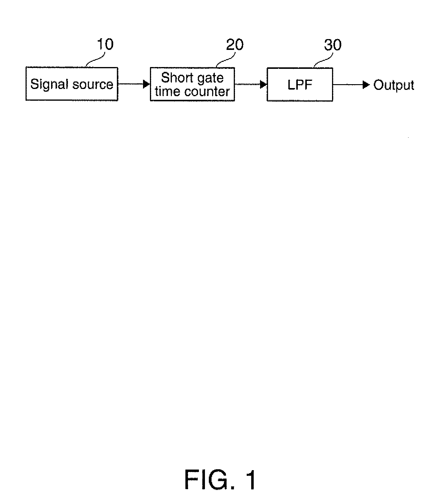
[0032]Preferred embodiments of the invention are described below with reference to the accompanying drawings. First, the outline of a frequency measuring device using a “short gate time count method” proposed in Laid-open patent application 2009-250807 is described with reference to FIGS. 1 through 7. Corresponding sections in the figures are appended with the same reference numbers.

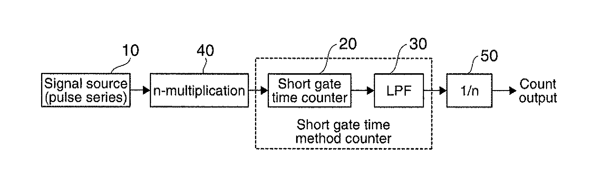
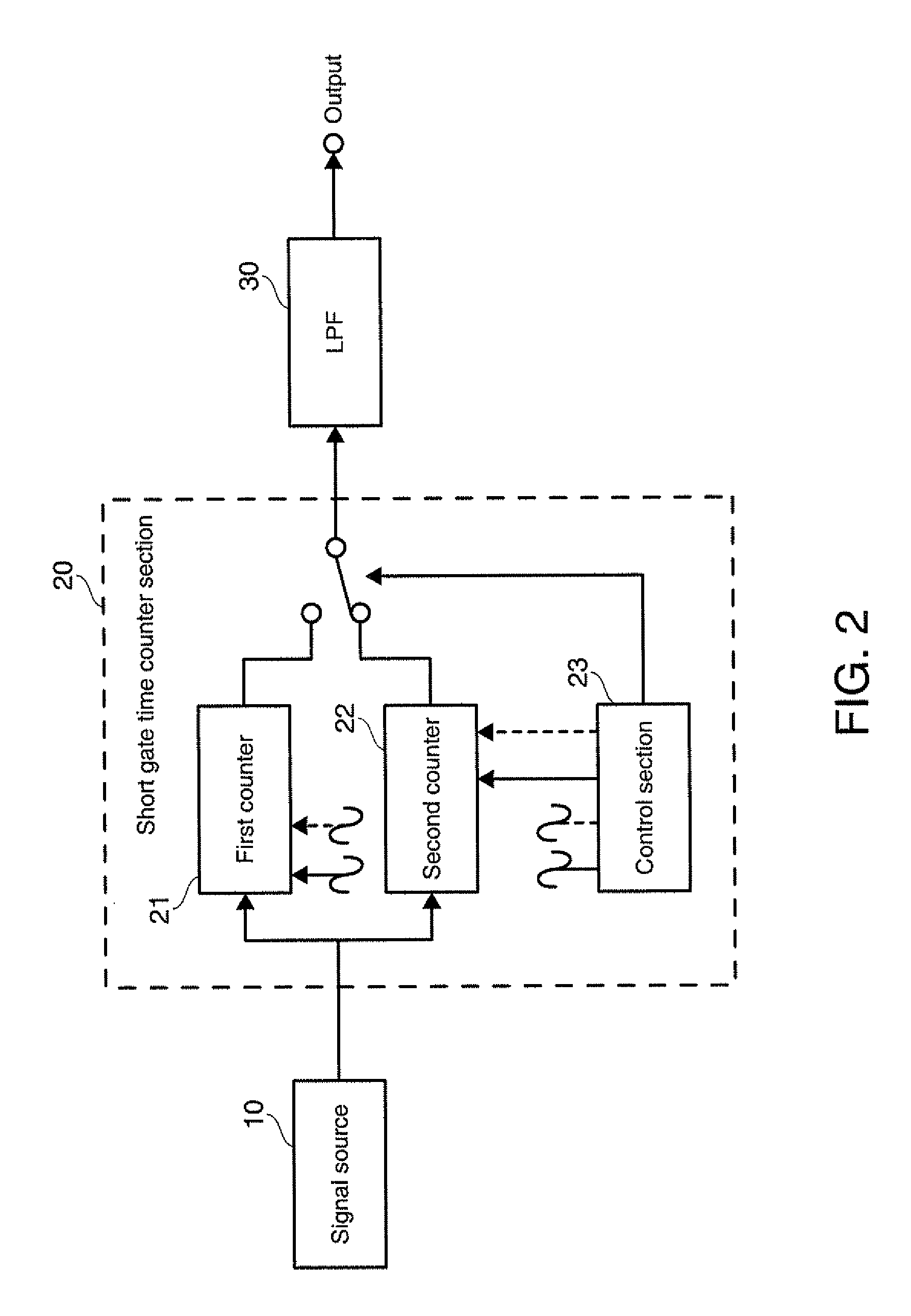
[0033]In FIG. 1, a signal source 10 generates a pulse stream signal. The signal source (a pulse generator) 10 may be, for example, a quartz oscillator with a predetermined frequency, for example, an oscillation frequency f0 at 30 MHz, and corresponds to a detector section of an odor sensor, a gas sensor, a biosensor and the like. When odor substance adheres to the quartz oscillator, its oscillation frequency lowers according to the amount of adhered substance. The pulse stream signal is supplied to a short gate time counter section (hereafter also simply referred to as a “short gate counter”) 20. The sho...


PUM


Abstract

A frequency measurement device for measuring a frequency of a signal to be measured including a pulse signal, includes: a signal multiplier section that multiplies the signal to be measured by n is an integer) and outputs a multiplied signal; a counter section that counts the multiplied signal with a predetermined gate time and outputs a count value of the frequency of the signal to be measured at a predetermined period; and a low-pass filter that outputs a signal corresponding to the frequency of the signal to be measured based on the count value outputted at the predetermined period.

Description

[0001]The entire disclosure of Japanese Patent Application No. 2009-121509, filed May 20, 2009 is expressly incorporated by reference herein.BACKGROUND[0002]1. Technical Field[0003]The present invention relates to measurement devices and, in particular to frequency measurement devices capable of detecting small changes in frequency.[0004]2. Related Art[0005]As frequency measuring systems, a direct count system in which pulses passing within a predetermined gate time are counted (see, for example, Published Japanese Translation No. HEI 06-501554 of the PCT International Publication), and a reciprocal system in which a pulse period is correctly measured, and the frequency is obtained by the reciprocal of the time. The direct count system may be realized with a relatively small-scale circuit, but needs a longer gate time to obtain a higher frequency resolving power (for example, a gate time necessary to obtain a resolving power of 0.1 Hz is 10 seconds). The reciprocal system can overco...

Claims


Application Information

Patent Timeline
IPC IPC(8): G01R23/02
CPCG01R23/10
Inventor TODOROKIHARA, MASAYOSHI
Owner SEIKO EPSON CORP
Why Eureka
Try Eureka