Ozone generating apparatus

a technology of generating apparatus and ozone, which is applied in the direction of relays, corona discharge, instruments, etc., can solve the problems of brush shaft deformation, significant heat generation, and increase of contact resistance between metal thin wires and metal films, so as to increase the heat generation of joules and increase the contact resistance. , the effect of high reliability

Active Publication Date: 2010-11-25
MITSUBISHI ELECTRIC CORP
View PDF4 Cites 7 Cited by
  • Summary
  • Abstract
  • Description
  • Claims
  • Application Information

AI Technical Summary

Benefits of technology

[0014]According to the present invention, an ozone generating apparatus comprises a power feeding brush comprising a brush shaft which is thickened and metal thin wires whose length are shortened. Therefore, even if the metal thin wires are melted by the short-circuit current or the increased joule's heat generation caused by the increased contact resistance, the temperature of the brush shaft is not increased to be its melting point. Consequently, the brush shaft will not be melted and a glass tube will not be damaged. As a result, the present invention can provide an ozone generating apparatus having high reliability.

Problems solved by technology

However, when a glass tube is degraded or damaged by some causes, short-circuit current flows from an alternating high voltage power supply into a metal film of the damaged glass tube.
Consequently, heat generation is a significant problem.
Further, there is a problem such that when a large current flows in metal thin wires, the metal thin wires are heated with joule heat to be a high temperature, and as a result, the metal thin wires are melted because stainless steel has a high resistivity and a high contact resistance.
Further, there is a problem such that a contact resistance between a metal thin wire and metal film increases due to deterioration caused by long-term operation such as oxidation, the metal thin wires are heated with joule heat to be a high temperature, and as a result the metal thin wires are melted.
Further, there is a problem such that when the temperature of a brush shaft is increased with the heat generated by melting the metal thin wires, the brush shaft is deformed so as to destroy the glass tube.
Under these conditions, other glass tubes of the apparatus are also destroyed.
In an ozone generating apparatus in which a fuse is not provided, in a case when power is supplied from an alternating high voltage power supply to a discharge tube again after short-circuit current is cut off, current concentrates on a metal film of the damaged tube again, therefore, operation of the apparatus can not be resumed.

Method used


Image

  • Ozone generating apparatus
  • Ozone generating apparatus
  • Ozone generating apparatus

Examples


first embodiment

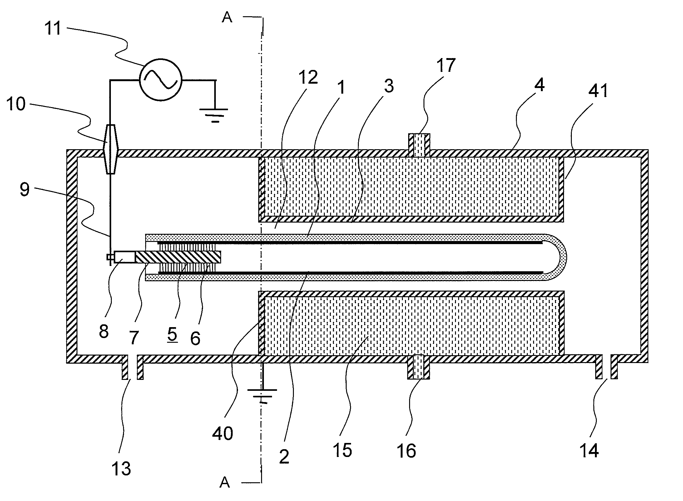
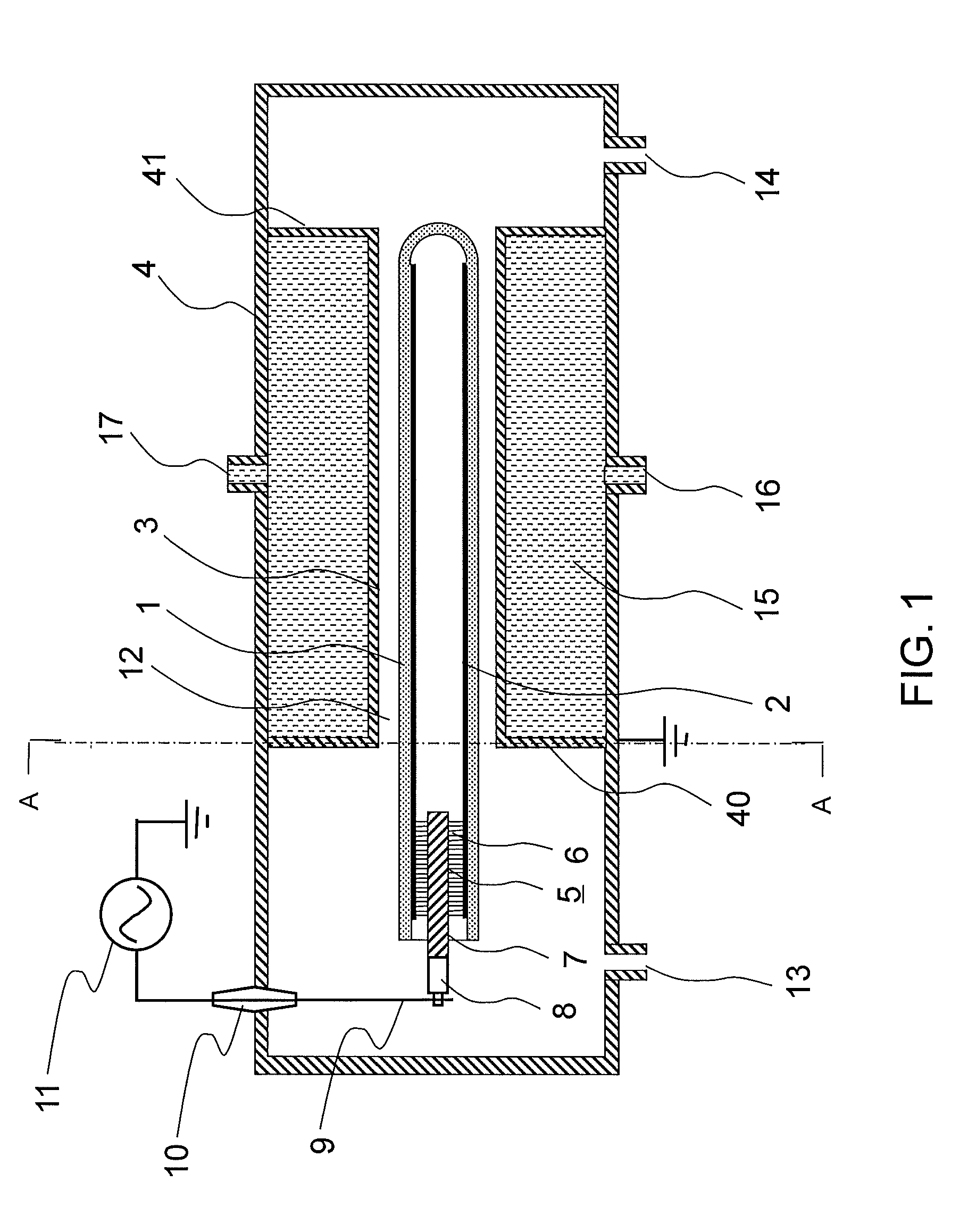
[0026]Hereinafter, first embodiment will be described referring to FIG. 1. FIG. 1 is a side cross sectional view showing a main part of the present invention. In order to describe the configuration, only one discharge tube is shown in FIG. 1, however, a large number of discharge tubes are arranged in parallel in an ozone generating apparatus according to the present invention.

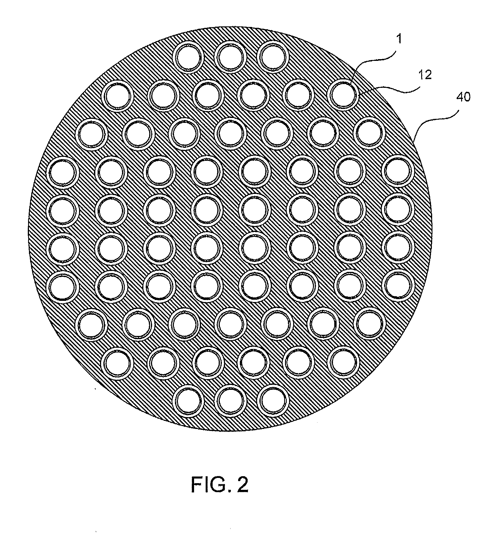
[0027]FIG. 2 is a view taken along the line A-A in FIG. 1 showing an ozone generating apparatus comprising a large number of discharge tubes which are arranged in parallel. In order to understand the configuration easily, in FIG. 2, the configuration in which 64 discharge tubes are arranged in parallel is shown, however, in an ozone generating apparatus according to the present invention, 100 or more discharge tubes are arranged in parallel.

[0028]A metal film 2 which functions as a high voltage electrode is formed in contact with the inner wall of a glass tube 1, and a cylindrical metal tube 3 which functions a...

second embodiment

[0049]Next, Second Embodiment of the present invention will be described referring to FIG. 4. A brush shaft comprises four strands 7a, 7b, 7c and 7d. Metal thin wires are sandwiched between four strands in a V shape or in an inverted-V shape, and then the four strands are twisted so as to form a brush. The total number of metal thin wires used in the configuration of FIG. 4 is same as that of FIG. 3. However, in the configuration of FIG. 4, metal thin wires are dispersed and electric current can be uniformly applied. When a power feeding brush is used for a long period, due to oxidation, contact resistance is increased on a surface where metal thin wires and a metal film are contacted. Consequently, electrical conductive performance degrades. When the configuration of FIG. 4 is adopted, electric current can be dispersed. Consequently, a degradation rate can be suppressed. Accordingly, an ozone generating apparatus having higher reliability and long-term life can be provided.

[0050]Fu...

third embodiment

[0051]Next, Third Embodiment of the present invention will be described referring to FIG. 5. A disc-shaped supporting member 20 made of ceramic is fixed to the brash shaft 7 of the power feeding brush 5. An outer diameter of the supporting member 20 is made to be slightly smaller than an inner diameter of the metal film 2. FIG. 6 shows the configuration where the glass tube is damaged, and metal thin wires 6 are melted and disappear.

[0052]In a damaged portion 21 of the glass tube 1, a hole is made, the electric potential of the metal film 2 becomes almost same as that of the metal tube 3 (ground). A high voltage is applied to the brush shaft 7. However, the brush shaft 7 is insulated from the metal film 2 while keeping a distance by the supporting member 20 made of ceramic and the power feeding member 9. Consequently, an ozone generating apparatus according to the present invention can be continuously operated. Accordingly, an ozone generating apparatus having high reliability can b...


PUM


Abstract

An ozone generating apparatus having high reliability in which a glass tube can prevent from being damaged by melting a power feeding brush even if a large amount of short-circuit current flows. In an ozone generating apparatus using silent discharge, an alternating high voltage power is supplied from a power supply to a metal film formed in an inner wall of a glass tube by a power feeding brush comprising a brush shaft made of metal and a large number of metal thin wires fixed to the periphery of the brush shaft, the following equation satisfies.
(D2/D1)≧(1+(1/20 β)),
    • wherein ‘D1’ indicates an outer diameter of a bundle of metal thin wires, ‘D2’ indicates an outer diameter of the brush shaft and ‘β’ indicates the line density of metal thin wires on a surface of the brush shaft.

Description

BACKGROUND OF THE INVENTION[0001]1. Field of the Invention[0002]This invention relates to an ozone generating apparatus by utilizing a silent discharge, particularly, relates to an ozone generating apparatus of a large capacity.[0003]2. Description of the Related Art[0004]Conventional ozone generating apparatuses have the configuration shown in FIG. 11. Conventional ozone generating apparatuses comprise a glass tube 1, a metal film 2 formed in an inner wall of the glass tube 1 so as to function as a high voltage electrode, a cylindrical metal tube 3 arranged outside the glass tube 1 coaxially with the glass tube so as to function as a grounding electrode. The metal tube 3 is fixed to an ozone generating tank 4 which is electrically grounded. A power feeding brush 30 is inserted inside the metal film 2, an alternating high voltage is supplied to the metal film 2 from an alternating high voltage power supply 11 provided outside the ozone generating tank 4 through a power feeding membe...

Claims


Application Information

Patent Timeline
Patent Type & Authority Applications(United States)
IPC IPC(8): B01J19/08
CPCC01B13/11C01B2201/76C01B2201/64
Inventor NAKATANI, HAJIMETAKAUCHI, DAISUKETAKEDA, TOMOAKITOKIMORI, KOICHI
Owner MITSUBISHI ELECTRIC CORP
Why Eureka
Try Eureka