
Backwash assembly and method having a rotating backwash arm for cleaning cloth filter media

a technology of cloth filter media and backwash arm, which is applied in the direction of filtration separation, sedimentation settling tank, separation process, etc., can solve the problems of poor quality effluent, chambers that had to be dewatered before maintenance could be carried out, and the filtration process at the stationary cloth media suffered a number of problems, so as to achieve high solids, high quality effluent, and high effluent quality

Inactive Publication Date: 2010-12-02
AQUA AEROBIC SYST
View PDF45 Cites 12 Cited by
  • Summary
  • Abstract
  • Description
  • Claims
  • Application Information

AI Technical Summary

Benefits of technology

[0013]For example, the present inventions provide higher quality effluent (even at high solids and hydraulic loading rates), lower backwash rates and higher capacity for a given basin footprint, when compared to conventional sand filters. They also eliminate sand or other granular media, making backwashing faster and more efficient. When compared to rotating disk-type or drum-type cloth media filtration systems, the present inventions provide, among other things, higher capacity while maintaining a comparably high quality effluent, continuous filtration during the backwash cycle and the elimination of the necessity for rotary disks and drums and their associated hardware. The present invention also provides more uniform flow distribution in the basin and over the filtration media, regardless of the type of filtration media used. The present inventions also improve the backwashing operation and reduce wear and break-through of cloth filter media for a variety of types of cloth media filtration.
[0042]Still yet a further object of the present invention is to provide processes and devices for backwashing cloth filter media that extend cloth filter media life by decreased wear rate; and,

Problems solved by technology

This attempt at stationary cloth media filtration suffered from a number of problems.
In addition, because of their design, the seals around the filtration screens were prone to leaks or failure, resulting in poor quality effluent.
Similarly, since most of the moving parts, such as the chain and sprocket system needed for backwashing, were submerged, the chambers had to be dewatered before maintenance could be conducted.
In short, this attempt at a cloth filtration system was very complicated and inefficient.
It is believed that the system was a failure and was abandoned.
This may result in increased wear and premature break-through of the cloth filter media.
More complicated control wiring is also required.
Conventional rotating cloth media filtration also has some inherent limitations.
Larger disks / drums require deeper and larger tanks, increasing their construction costs.
The retrofit or construction of smaller tanks requires smaller disks, which reduces the filtration surface area.
Again, regardless of the type of filtration media used, uneven flow distribution over the volume of the filtration basin or region is a potential problem.
For example, uneven or non-uniform flow distribution within the filtration basin or region often results in sludge settling, particularly in areas of low turbulence.
This often results in the need for additional sludge removal equipment or increased system down time.
In addition, non-uniform flow velocity across the filter may also result in increased sludge settling.
Thus, while the conventional deep bed sand and rotating disk filtration systems generally described above have been widely and successfully used in a variety of applications, each of these systems suffer from drawbacks inherent in or related to their size, design and / or application.

Method used


Image

  • Backwash assembly and method having a rotating backwash arm for cleaning cloth filter media
  • Backwash assembly and method having a rotating backwash arm for cleaning cloth filter media
  • Backwash assembly and method having a rotating backwash arm for cleaning cloth filter media

Examples


Embodiment Construction

[0110]Set forth below is a description of what is currently believed to be the preferred embodiments or best representative examples of the inventions claimed. Future and present alternatives and modifications to the preferred embodiments are contemplated. Any alternatives or modifications which make insubstantial changes in function, purpose, structure, use or result are intended to be covered by the claims of this patent.

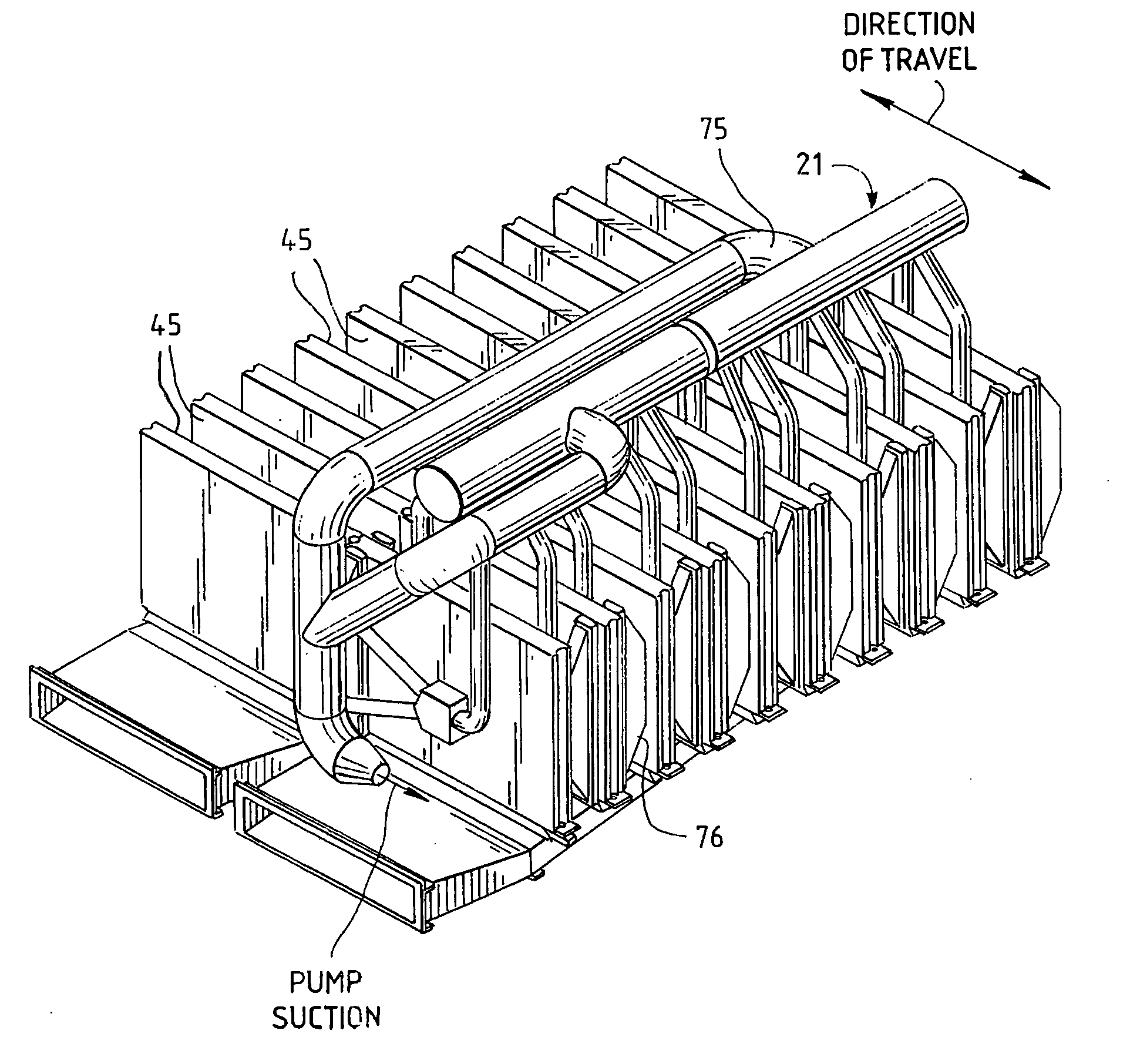
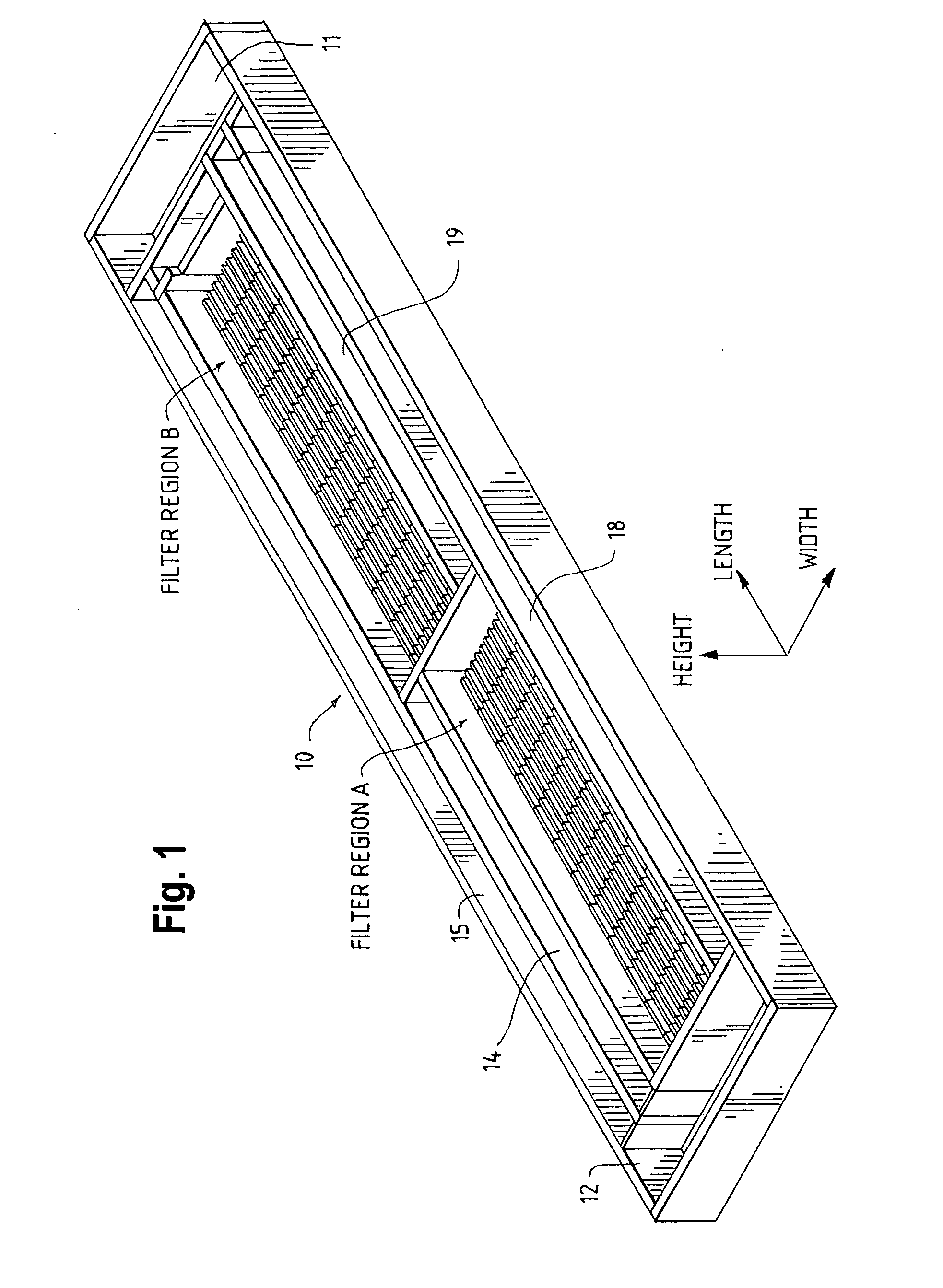
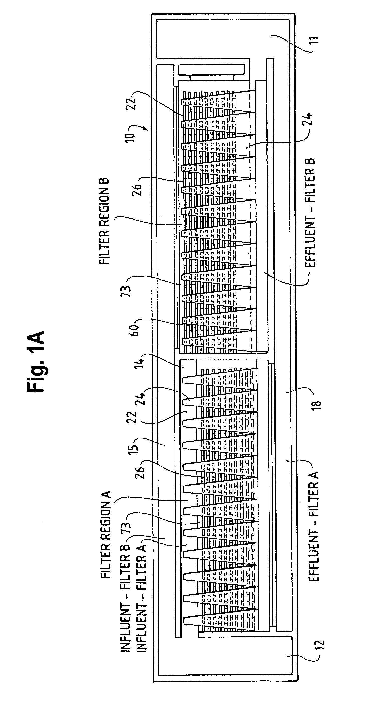
[0111]The general layout of a typical configuration of one embodiment of the present invention may be seen by reference to FIGS. 1 and 1A. The present invention may be designed to fit into the footprint of an existing filtration basin to replace, for example, a granular media gravity filtration system. It may also be designed for a completely new facility, or installed in a tank arrangement similar to conventional disk filtration. Moreover, many aspects of the present invention may be applicable to other water and wastewater treatment methods.

[0112]The present inv...


PUM

PropertyMeasurementUnit
cause selective rotationaaaaaaaaaa
suctionaaaaaaaaaa
gravityaaaaaaaaaa

Abstract

The present invention relates to stationary cloth media filtration systems and devices, as well as processes and devices, including improved cloth media filter backwashing using a rotating backwash arm assembly.

Description

RELATED APPLICATIONS[0001]This application is a continuation-in-part of U.S. application Ser. No. 11 / 005,561 filed on Dec. 6, 2004, now pending, which is a divisional of application Ser. No. 10,329,630, filed on Dec. 6, 2002, which issued as U.S. Pat. No. 6,858,140 on Feb. 22, 2005, all incorporated herein.FIELD OF THE INVENTION[0002]The present invention relates generally to water and wastewater treatment processes. More particularly, the present invention relates to stationary cloth media filtration systems and devices, as well as processes and devices for uniform flow distribution and backwashing.BACKGROUND OF THE INVENTION[0003]There are a variety of established water and wastewater treatment systems. One type that has been in use for decades, in one form or another, is granular media gravity filtration. Granular media gravity filters, such as conventional deep bed sand filters, are used to strain out particles from a wastewater stream. Typically, wastewater is introduced into a...

Claims


Application Information

Patent Timeline
Patent Type & Authority Applications(United States)
IPC IPC(8): B01D29/68
CPCB01D29/39B01D2201/44B01D29/52B01D29/688B01D29/96
Inventor BAUMANN, PETER G.SMITH, DAVID
Owner AQUA AEROBIC SYST
Learn More