
Transport Container

a technology for transporting containers and containers, applied in the field of transporting containers, can solve the problems of air transport, difficult positions for transport managers, and damage to goods, and achieve the effect of easy construction, low cost and easy manufacturing

Active Publication Date: 2010-12-02
SOFTBOX SYST LTD
View PDF10 Cites 34 Cited by
  • Summary
  • Abstract
  • Description
  • Claims
  • Application Information

AI Technical Summary

Benefits of technology

[0014]The present invention seeks to provide a solution to the problems addressed above. The present invention seeks to provide a transport container which can be manufactured at low cost and can readily and easily be constructed. The present invention seeks to provide a transport container which can be erected at point of use. Furthermore, the present invention seeks to provide a container that when completed can maintain goods within a narrow temperature range.
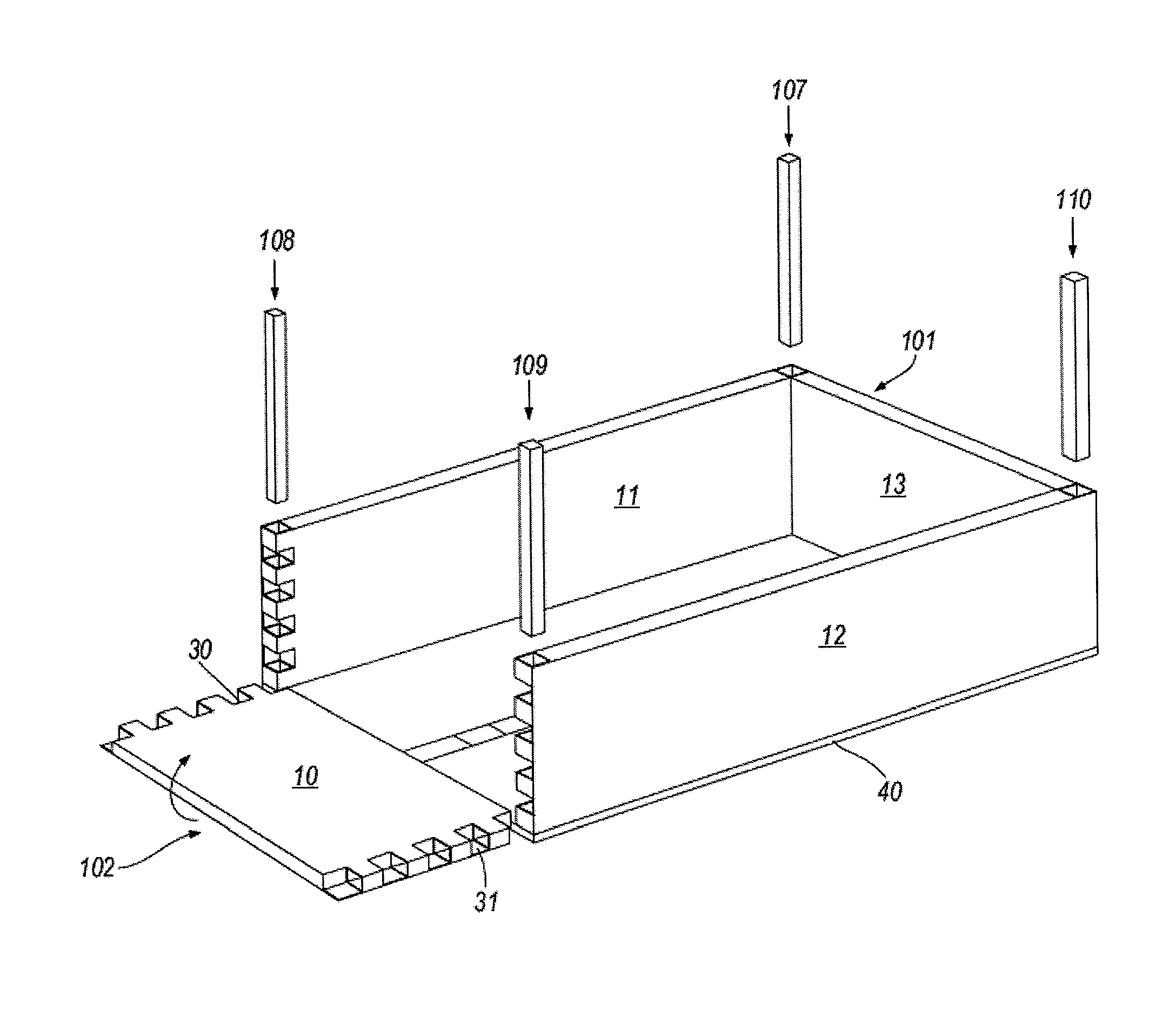
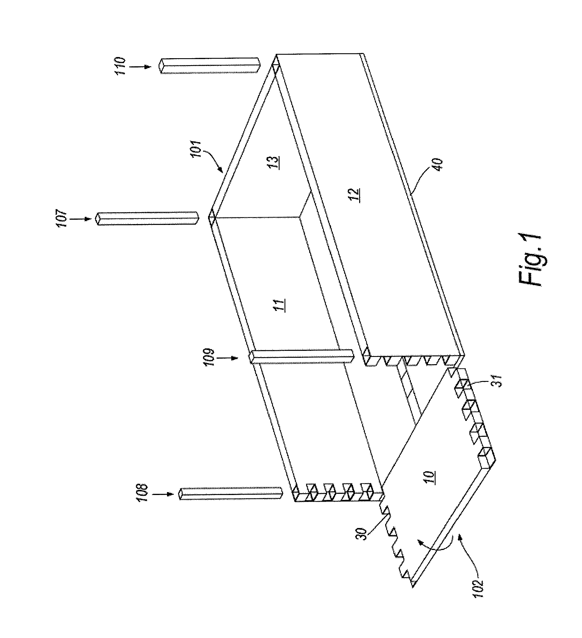
[0016]In accordance with a general aspect of the invention, there is provided a thermally insulating collapsible transport container fabricated from at least one set of co-operating first and second panels arranged substantially at right angles to one another, the first and second panels having first (outside) and second (inside) major surfaces and a circumferential edge portion, wherein a first panel defines a rebated channel on an inside face of the panel, the channel being adjacent to at least one edge, the rebate being defined in cross-section by an edge face of the panel and a general L-shape, a first arm of the L-shape section defining, in use, part of the outside wall of the first member, the second arm of the L-shape section having an inside face opposing said edge face of the panel, whereby to define a rebate into which an edge portion of the second panel can be received and resiliently retained therein. By having separate panels resiliently retained, air passage between an inside and an outside of a container is prevented.
[0017]Conveniently, the container comprises at least a base and upstanding wall panels, wherein the base panel corresponds to the first panel type and the wall panels correspond to the second panel type. Conveniently, the panels are of rectangular shape in plan view. The container can have a variety of forms, but a rectangular box would be the most frequently employed, even though it would be possible to have square section or cylindrical section boxes; indeed, the walls could be non-vertical, at least in part. Preferably, the container further comprises one or more insulating cover panels, which insulating cover panels correspond in type with either the first or second panel type, whereby the cover panel can be resiliently retained with respect to an upstanding wall panel. By having separate panels resiliently retained, air passage between an inside and an outside of a container is prevented.
[0023]The base, sidewall and top members are conveniently flat panels, made of extruded polystyrene, expanded polyurethane or polyethylene foam. Conveniently, the foam panels are laminated whereby to provide optimum rigidity, with a light weight, with good thermal barrier properties. Ideally, the edges of any adjoining co-planar panel members have complimentary rebates. An advantage arising from the use of materials such as polyethylene foam means that thermal insulation and physical shock protection is extremely high with regard to known container systems. The L-section member can be integrally moulded, using a glass reinforced plastics material exterior laminate, which is secured to plastics foam elements, for insulation.

Problems solved by technology

Food and pharmaceutical products not only need protection from physical shock and pressures but also require temperature stability during transportation; otherwise goods can be damaged and be unusable, whether such damage is apparent or not.
However, air transport poses a particular problem: Goods can be transported in tropical heat, packaged and placed upon pallets and the like containers whereby they are presented in aircraft style containers.
Both the above scenarios place transport managers in difficult positions.
Glass-fibre-reinforced plastics panels are combined with steel components to provide an assembly which whilst strong is not capable of being dismantled.
The panels provide a limited amount of temperature insulation, especially taking into account the relatively large size of the cardboard panels, being approximately 15 cm thick.
Whilst this solution provides a strong and rigid—yet resilient—container, when empty the container takes as much space as when full, which is not acceptable for many supply industries.
Furthermore, by providing an enclosure, limitations are placed with respect to the order of packing and the addition of goods to be despatched, which can provide complications and expense to any freight manager.
It is notable that there are few thermally insulating cargo containers; either they are rigid yet not collapsible or are collapsible yet easily damaged when shifted by fork-lifts and other and / or are complex to assemble.

Method used


Image

  • Transport Container
  • Transport Container
  • Transport Container

Examples


Embodiment Construction

[0038]There will now be described, by way of example only, the best mode contemplated by the inventor for carrying out the present invention. In the following description, numerous specific details are set out in order to provide a complete understanding to the present invention. It will be apparent to those skilled in the art, that the present invention may be put into practice with variations of the specific.

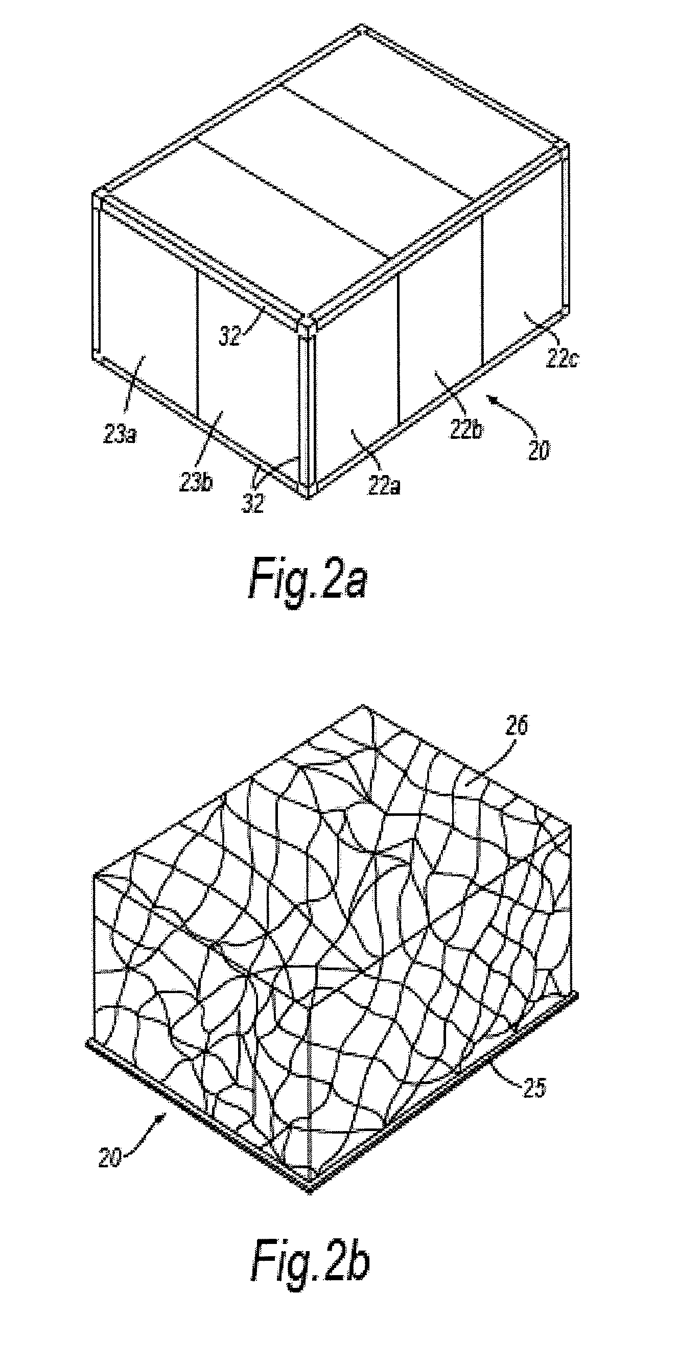
[0039]FIG. 2 shows a first embodiment 20 of the invention in an assembled state. Whilst a base panel is not shown in any detail, outwardly extending the L-section corner sections (to be referred to as L-members hereinafter) 32 depending from the base panel are shown. These L-members are derived from corner guards as used in the packaging industry, (where they are also referred to as V-boards) which are typically retained in place with plastics wrapping film and or polystyrene mouldings about a package.

[0040]The top panels, in this embodiment correspond from an outward perspect...


PUM

PropertyMeasurementUnit
Temperatureaaaaaaaaaa
Widthaaaaaaaaaa
Contentaaaaaaaaaa

Abstract

The present invention relates to a transport container which provides mechanical and thermal stability for a load and which container is fabricated as the container is loaded. In particular, the present invention relates to a container which can be readily transported on aircraft, such as an aircraft container. In the field of logistics, that is the field of movement and supply of produce and materials, in particular in the transport of intermediate and finished products, containers have been developed which safely protect from physical damage a wide variety of product. Food and pharmaceutical products not only need protection from physical shock and pressures but also require temperature stability during transportation; otherwise goods can be damaged and be unusable, whether such damage is apparent or not. However, air transport poses a particular problem: Goods can be transported in tropical heat, packaged and placed upon pallets and the like containers whereby they are presented in aircraft style containers. Such goods may be left on runways at extreme temperatures (+40° C.) and then placed within a hold where low pressures and low temperatures exist during flight. At a destination airport the temperatures may well be sub-zero. To simplify transport with respect to airports, planes and handling equipment, there have been developed aircraft Unit Load Devices (ULDs) which comprise any type of pallet or container that can easily be loaded to the aircraft by a ground handler. The present invention seeks to provide a transport container which can maintain goods within a narrow temperature range, can displace a considerably reduced volume before erection, is economical to manufacture, can readily and easily be constructed. The present invention further seeks to provide a transport container which is compatible with standard Unit Load Device specifications.

Description

FIELD OF INVENTION[0001]The present invention relates to a transport container which provides mechanical and thermal stability for a load and which container is fabricated as the container is loaded. In particular, the present invention relates to a container which can be readily transported on aircraft, such as an aircraft container.BACKGROUND TO THE INVENTION[0002]In the field of logistics, that is the field of movement and supply of produce and materials, in particular in the transport of intermediate and finished products, containers have been developed which safely protect from physical damage a wide variety of product. Food and pharmaceutical products not only need protection from physical shock and pressures but also require temperature stability during transportation; otherwise goods can be damaged and be unusable, whether such damage is apparent or not.[0003]For example, in the pharmaceutical industry, product often needs to be maintained within a temperature range: product...

Claims


Application Information

Patent Timeline
IPC IPC(8): B65D81/38B65D6/24B65D25/54B23P11/00
CPCB65D88/528B65D81/3827B65D90/06Y10T29/49826B65D90/00F25D2303/08221F25D3/06F25D2500/02B65D90/023B65D88/14B65D90/08B65D81/3834
Inventor TATTAM, EDWIN FRANCISJONES, RICHARD WILLIAM
Owner SOFTBOX SYST LTD
Learn More