Wind power device

Inactive Publication Date: 2010-12-02
DAWOUD GUIRGUIS SAAD +1
View PDF8 Cites 18 Cited by
  • Summary
  • Abstract
  • Description
  • Claims
  • Application Information

AI Technical Summary

Benefits of technology

[0014]A slowly rotating wind wheel rotates about a shaft supported on a high tower. The semi flexible sails catch the wind and provide rotational force. The rotational force forces the rim to rotate. The shaft supporting the rim is fixed on top of a two piece tower that has beari

Problems solved by technology

Wind energy is widely available but is a dilute form of energy.
Previous vertical shaft turbine designs proved uneconomic and achieved limited success.
These factors combined narrows the choice of materials to expensive fiber reinforced composites.
These also require a very expensive and accurate die to manufacture a 60 meter long blade.
Unfortunately, the tip speed is still fairly high (around 70 m/s) resulting in high frictional [drag] losses to the air.
Due to these factors and complications, the yaw drive/slew ring system cost is a considerable portion of the total cost of a large WTG.
5—Blade pitch system: Similarly, High bending moment of the cantilevered blades, requires a precise and expensive yaw system for each in

Method used


Image

  • Wind power device
  • Wind power device
  • Wind power device

Examples


Embodiment Construction

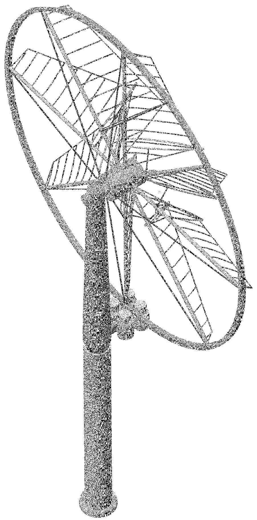
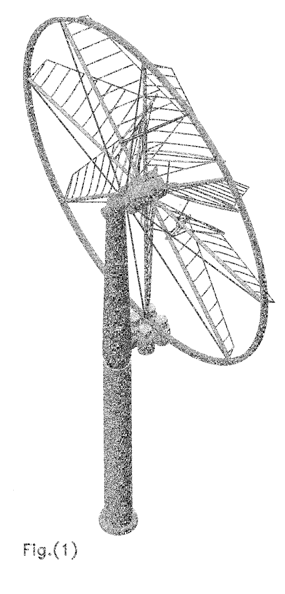
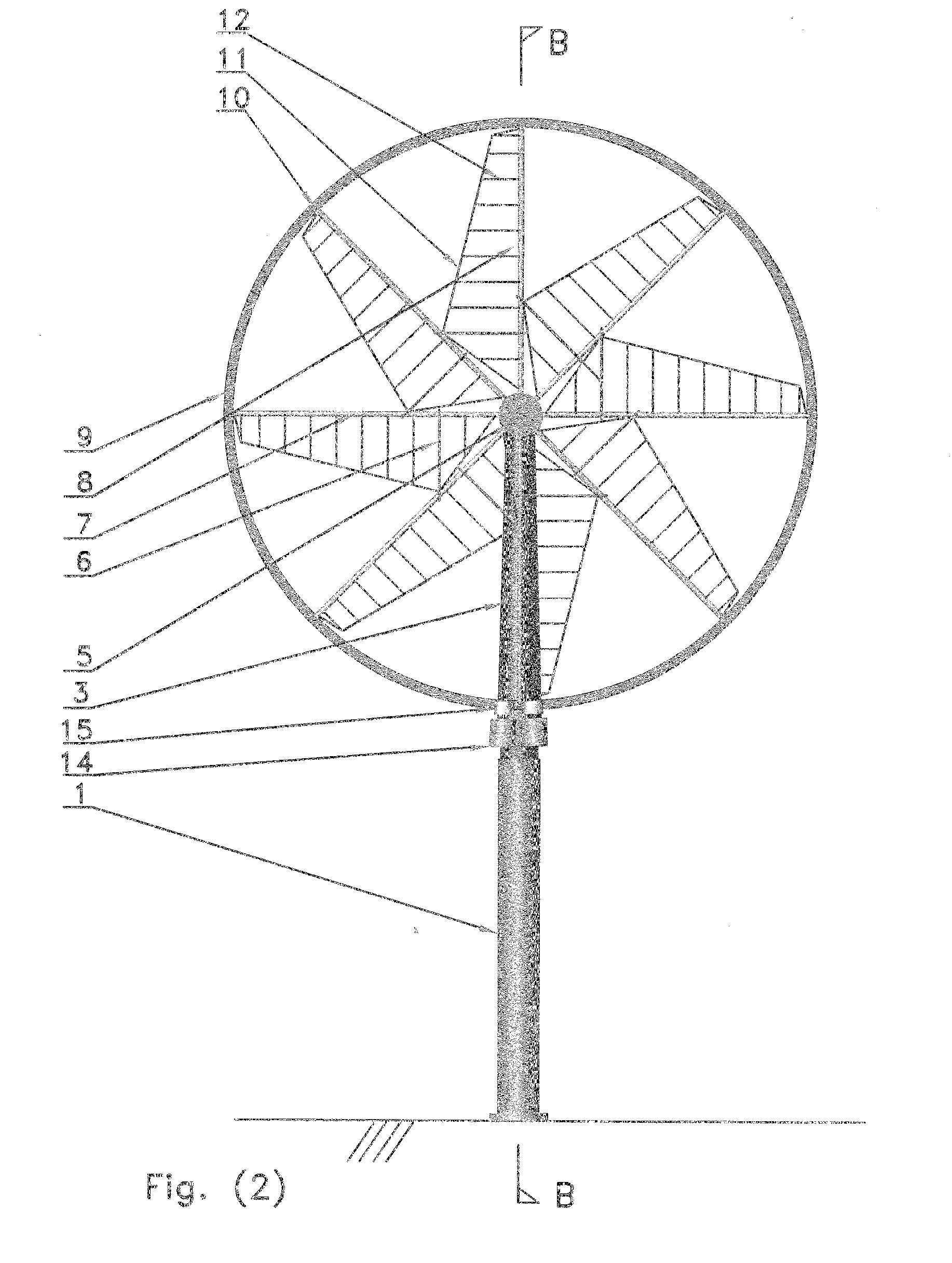
[0021]The Rim, Hub, and Spokes:

[0022]Our design consists of a very large diameter rim (9) connected to a hub (14). The hub (14) and the rim are connected by a multitude of poles or spokes(7). These spokes may be supported by tensile elements or wires(8) at an angle to the spokes on the upwind side of the spokes. The tensile elements thus bear all the large horizontal force generated by the wind, and thus reducing the bending at the spoke root to a minimum. Some of the spokes or poles go through the sails (the lift generating surfaces) (11) chord or the blade's chord and is connected to it such that when the spokes rotate along their longitudinal axis, the sail's angle of attack changes accordingly. The connection between the spokes (10) and the rim or the hub, can be very simple bushings, or a flexible material that allows a certain measure of twist, similar to the root support of a windsurf sail. A slew ring on the wing root is not required. The rim supported by the spokes, with th...


PUM


Abstract

A new reduced cost easily manufactured light weight wind turbine design combining the use of downwind passive yaw, large take off rim on the outside of the semi rigid sails, a new method of furling or changing sail AOA, new semi rigid sail design, and new tower design that allows passive yaw for high installation of wind wheels to gain energy from higher wind speeds.
Combining these features dramatically lowers weight/simplifies manufacture/avoids need for expensive composite materials/avoids the need for heavy high reduction gearboxes/reduces friction losses to air/reduces noise/reduces bird strikes/catches more energy per area of sails/and ultimately reduces cost in US$ per kwh generated ratio.

Description

REFERENCES [0001]4,319,865March 1982Richard4,729,716March 1988Schmidt6,064,123May 2000Gislason20060275121December 2006Merswolke20070166159July 2007WilliamsBACKGROUND OF THE INVENTION [0002]With the current climate change crisis and energy demand rising, the world is looking for wind power to provide a bigger share of the energy demand. Wind energy is widely available but is a dilute form of energy. Turbine blades have to be large to catch enough kinetic energy from the low density air medium. Energy production is also an economic investment; the bottom line for the success of any wind turbine design, is the cost to power produced ratio ($ / kwh).[0003]It is the object of this patent to design a wind wheel style turbine that give a better cost to power ratio ($ / kwh) than all the presently available WTG's (Wind turbine generators) by a wide margin. This is achieved through a design that is lighter in weight, uses less expensive materials, easier to manufacture, and at the same time has ...

Claims


Application Information

Patent Timeline
IPC IPC(8): F03D7/04F03D9/00
CPCF03D1/065F03D7/0236F05B2220/7066F05B2240/2211F05B2240/3121F05B2240/33Y02E10/721Y02E10/723Y02E10/725Y02P70/523Y02E10/72Y02P70/50
Inventor DAWOUD, GUIRGUISYACOUB, ANNETTA ATTIA
Owner DAWOUD GUIRGUIS SAAD
Why Eureka
Try Eureka