Ocean wave energy converter capturing heave, surge and pitch motion

Inactive Publication Date: 2010-12-09
ROHRER TECH
View PDF26 Cites 31 Cited by
  • Summary
  • Abstract
  • Description
  • Claims
  • Application Information

AI Technical Summary

Benefits of technology

[0011]According to embodiments of the present invention, one or more gas tight containers are submerged to a depth slightly below anticipated wave and swell troughs. The container(s) have a fixed depth rigid end or surface held at relatively fixed depth relative to the water body mean water level or wave troughs by either a flexible anchoring means, with horizontal depth stabilization discs or drag plates, or by a rigid sea bed attached spar or mast, or the bottom itself. A second movable rigid end or surface opposes said first fixed end or surface. Said fixed and movable ends are separated and connected by and sealed to a flexible, gas tight, reinforced, elastomer or flexible metal bellows, or a diaphragm or accordion pleated skirt also suitably reinforced against collapse from container internal vacuum or external hydrostatic pressure. Overhead waves and troughs produce hydrostatic pressure variations which compress and expand said containers, respectively, bringing said movable end closer to and further from said fixed depth end. Container expansion and contraction (or “stroke”) is enhanced by either partial evacuation of said container or venting of said containers' gas to a floating surface atmospheric vent or to a floating surface expandable bellows or bladder, or reservoir. Without said partial evacuation or atmospheric venting, said stroke and hence energy capture would be reduced several fold. The relative linear motion between said containers' fixed and movable ends is connected to and transferred to a hydraulic or pneumatic pumping means or, mechanical or electrical drive means. The pressurized fluid flow from said hydraulic or pneumatic pumping can drive a motor or turbine with electric generator. Mechanical means can direct drive a generator via rack and pinion gearing, oscillating helical drive or other oscillating linear one or two way rotational motion means. Electrical drive means can be by a linear generator. After compression return and expansion of said containers and its' movable end can be assisted by mechanical (i.e. springs) pneumatic (compressed gas), hydraulic or electric means. Efficiency can be further enhanced by delayin

Problems solved by technology

The rolling membrane seal limits stroke and, therefore, energy capture and is vulnerable to frictional wear between the piston and cylinder and near shore debris caught within the seal.
Twin chamber devices spaced one average wavelength apart are inherently inefficient as wavelengths are very seldom at their average value.
Shallow water sea bed mounted devices must be rugged and therefore costl

Method used


Image

  • Ocean wave energy converter capturing heave, surge and pitch motion
  • Ocean wave energy converter capturing heave, surge and pitch motion
  • Ocean wave energy converter capturing heave, surge and pitch motion

Examples


Embodiment Construction

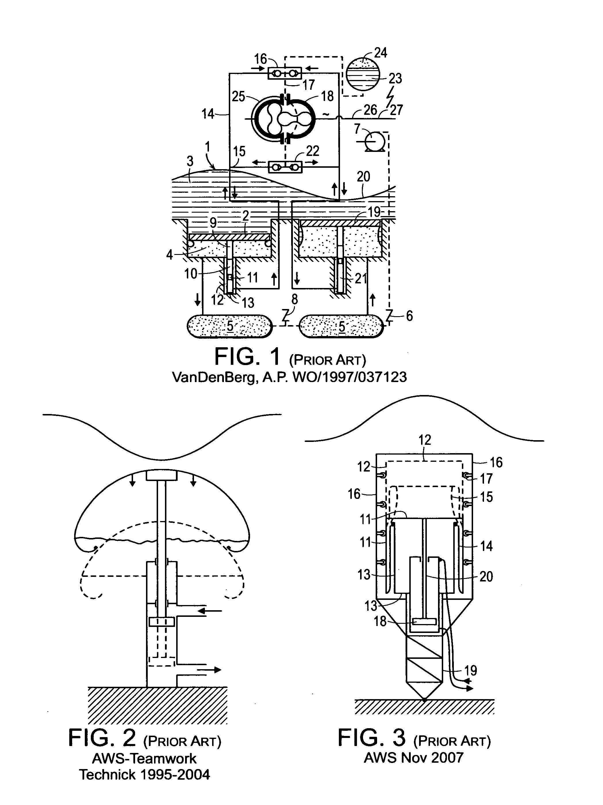
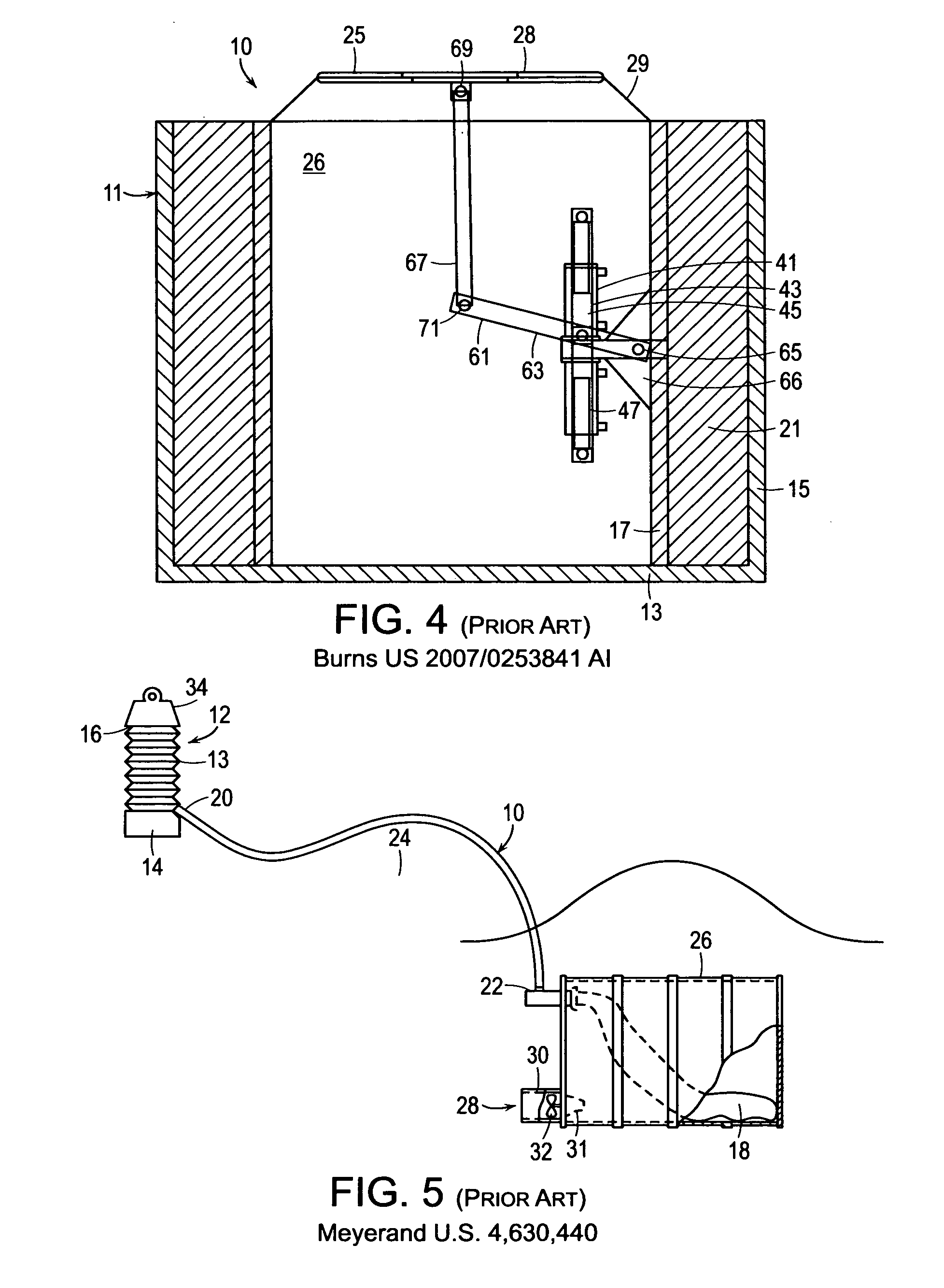
[0050]FIGS. 1-5 show prior art previously discussed. FIG. 6 shows a preferred embodiment of U.S. patent application Ser. No. 12 / 454,984 (FIG. 15) incorporated herein by reference and of which this application is a Continuation-in-Part.

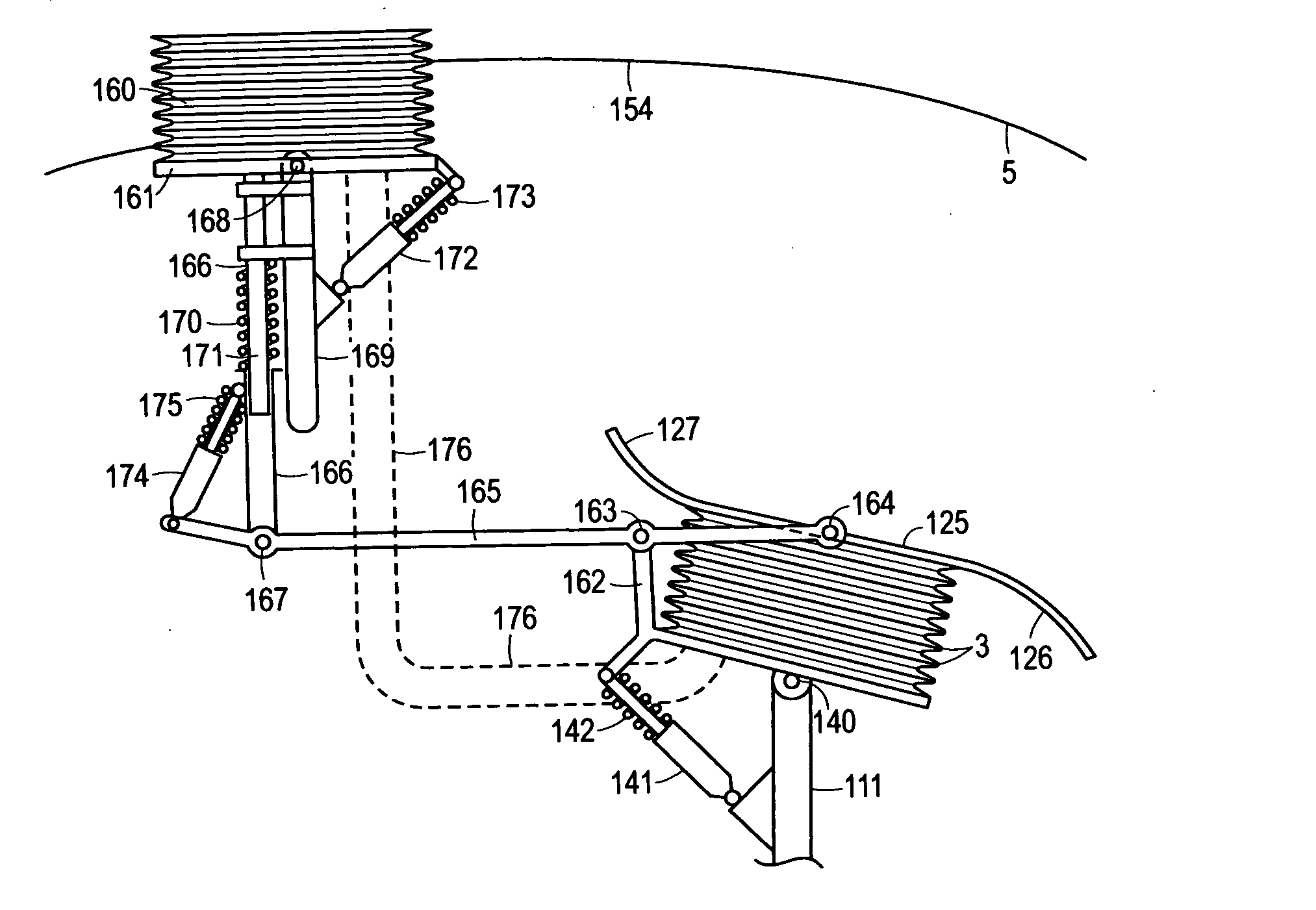
[0051]FIG. 7 shows an embodiment of the present invention similar to FIG. 6. Stationary surface 1 (sealed to a reinforced flexible bellows 3) is part of a molded or fabricated lower hull 100 which may have integral buoyancy chambers 101. Moving surface 2 is part of upper hull 102 which may also contain buoyancy chambers 101 which may also serve as expansion chambers. Flexible bellows 3 is supported against external hydrostatic pressure and, optionally internal partial vacuum, by (internal only) support rings 6. Bellows expansion return is via return spring 44 which return can be assisted or replaced by the 3 stage telescoping hydraulic drive cylinder 103. Bellows internal support rings 66 could be replaced by a helically wound spring (not shown) also s...


PUM


Abstract

An ocean wave energy device uses large gas filled and surface vented or partially evacuated flexible containers each having rigid movable ends and rigid fixed depth ends connected by flexible bellows, suitably reinforced against external hydrostatic pressure, submerged to a depth below anticipated wave troughs. One or more said containers compress and expand as waves and troughs, respectively, pass overhead driving hydraulic or pneumatic, pumping means producing pressurized fluid flow for a common sea bed motor-generator or for other uses or on-board direct drive generators. Mechanical, hydraulic or pneumatic means re-expand said containers when a wave trough is overhead. Power output is augmented by mechanically connecting said rigid moving surfaces to surface floats, which may also provide said submerged container venting such that as waves lift and troughs lower said floats, said containers are further compressed and re-expanded, respectively. Power output is further augmented by wave kinetic energy capture through focusing, reflection and refraction.

Description

FIELD OF INVENTION[0001]This invention relates to devices for producing electrical power, pressurized water or other useful work from surface waves on a water body.[0002]More particularly, this invention relates to wave energy converters wherein either all or a substantial portion of the energy captured or produced is from one or more submerged devices relying on overhead wave induced subsurface differences in hydrostatic pressure and / or enhanced surge or pitch which expand and contract or otherwise deform or deflect one or more gas filled submerged containers, thereby producing useful work. Such expansion and contraction is enhanced or supplemented by wave focusing, reflection or diffraction techniques and / or by overhead surface floating bodies.BACKGROUND OF THE INVENTION[0003]Wave energy commercialization lags well behind wind energy despite the fact that water is several hundred times denser than air and waves remain for days and even weeks after the wind which originally produce...

Claims


Application Information

Patent Timeline
IPC IPC(8): F03B13/18
CPCF03B13/1815F03B13/188Y02E10/38F05B2260/406F03B13/24Y02E10/30
Inventor ROHRER, JOHN W.
Owner ROHRER TECH
Why Eureka
Try Eureka