Light source for projection system and projection display apparatus

a technology of projection display and projection system, which is applied in the direction of projectors, color television details, instruments, etc., can solve the problems of reducing the overall quality of images, prior art increasing the brightness of red color at the cost of contrast and color saturation, and not meeting the illumination requirements of the projection system, etc., to achieve the effect of improving the brightness of red light, improving color saturation, contrast and other performances, and high practical valu

Inactive Publication Date: 2010-12-09
ACAD OF OPTO ELECTRONICS CHINESE ACAD OF SCI +1
View PDF13 Cites 60 Cited by
  • Summary
  • Abstract
  • Description
  • Claims
  • Application Information

AI Technical Summary

Benefits of technology

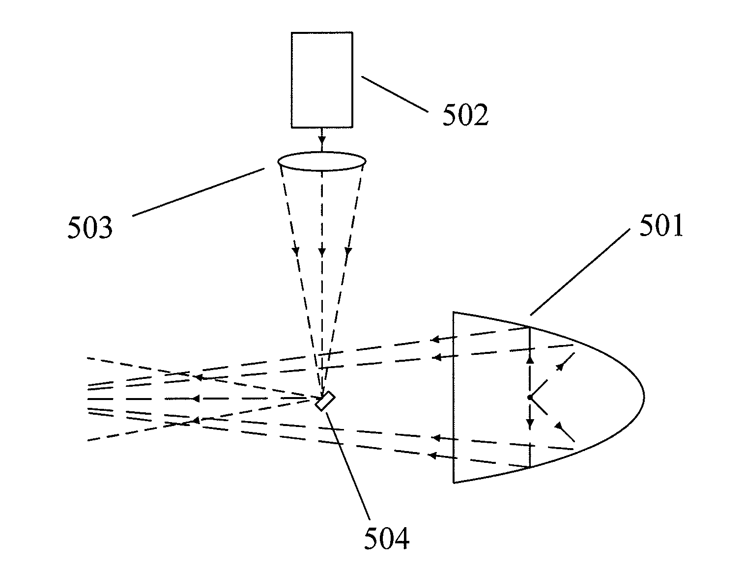
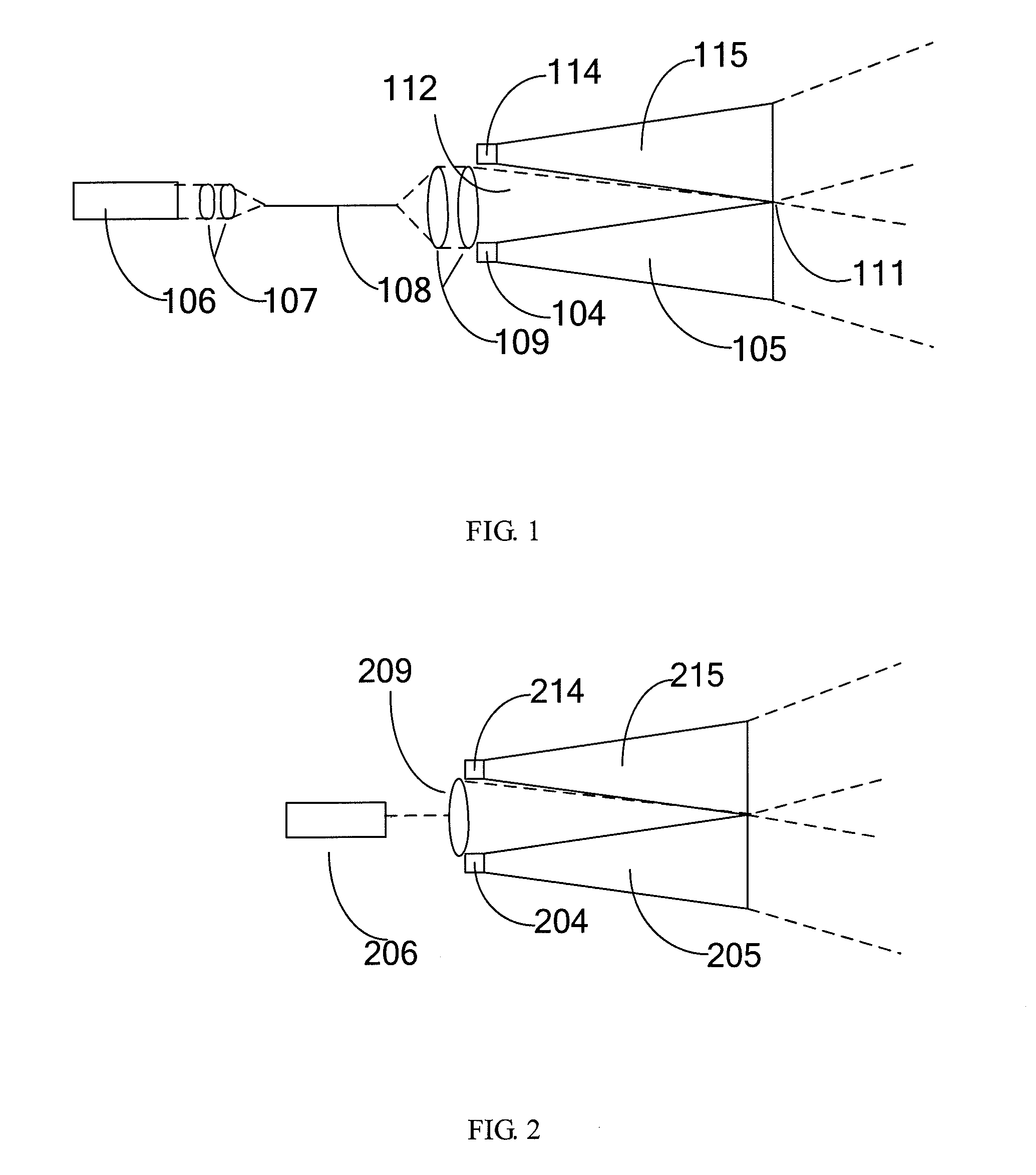
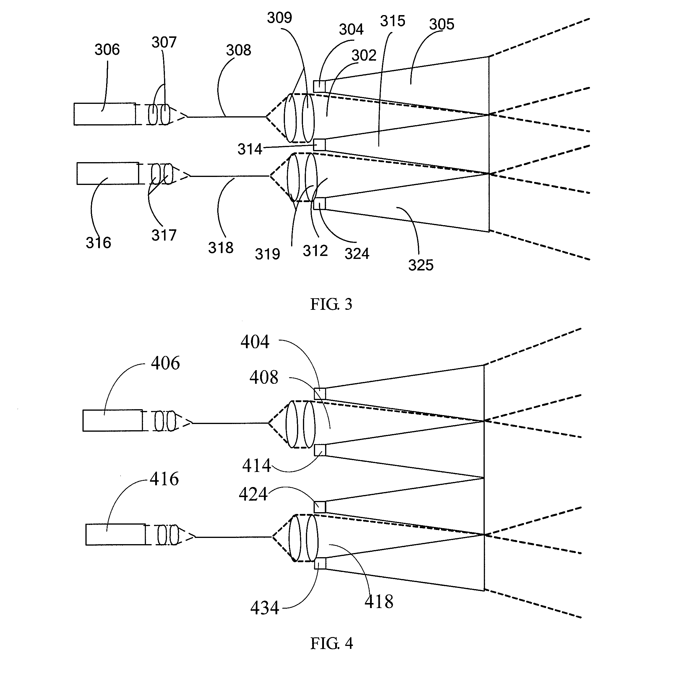
[0035]By using the foregoing technical solutions, the defect of inadequate illumination of red light emitted from ultra high-pressure mercury lamps, metal halide lamps, xenon lamps, halogen lamps and other lamps may be overcome, the brightness of red light is improved, the intensity distribution of three primary colors—red, green and blue is adjusted, the color saturation, contrast and other performances are improved, thus the above technical solution have a very high practical value in the field of projection display.
[0036]By using the foregoing technical solutions, the laser with high brightness and small optical etendue may be used

Problems solved by technology

Therefore, the ultra high-pressure mercury lamp may not meet the requirements of a projection system on illumination.
Moreover, during processing of video signals, the prior art increases the brightness of red color also at the cost of contrast and color saturation.
Therefore, although the prior art may soften the color of images, the overall quality of the images declines.
However, owing to the large optical etendue and low brightness of LED, the existing technology for LED illumination has the defects of low optical energy efficiency and low output optical power in total.
Although the luminous flux and brightness of LED have been increased remarkably, they are not yet sufficient for applications to projectors, particularly to the situations requiring high illuminating brightness.
To meet the requirements of applications to projectors and raise illuminating brightness, the prior art raises luminous flux and brightness by arrangement and combination of LEDs, but as LEDs are Lambertian light sources, if the optical etendue of the combined LED light sources exceeds the optical etendue of a projection system, the excessive light

Method used


Image

  • Light source for projection system and projection display apparatus
  • Light source for projection system and projection display apparatus
  • Light source for projection system and projection display apparatus

Examples


Embodiment Construction

[0063]As the spot and divergence angle of laser are both small, the optical etendue of laser is small. The optical etendue of the laser output from an optical fiber is determined by the following equation:

Elaser=π2r2 sin2 θ

[0064]Where, r is the radius of the fiber bundle, and sinθ is the numerical aperture of the optical fiber. The fiber bundle is combined by one or more optical fibers.

[0065]For example, the optical etendue of the laser output from a fiber bundle with r=0.35 mm and sinθ=0.22 is only 5.22×10⁻² mm2sr, more than two orders of magnitude lower than that of LED. The luminous flux under this optical etendue may reach several thousand lumens to ten thousand lumens. Therefore, for laser, high output of luminous flux can be obtained with small optical etendue.

[0066]In a hybrid light source with an LED and a laser, provided that the optical etendue of LED is Eled, the optical etendue of a laser is Elaser and the total optical etendue of the hybrid light source is Etotal which ...


PUM


Abstract

The present invention provides a light source device for projection display, comprising a light source to be supplemented and a laser light source. The laser emitted from the laser light source and the light emitted from the light source to be supplemented are mixed and then output in a same direction.

Description

FIELD OF THE INVENTION[0001]The present invention relates to a light source device and a projection display device, particularly to a light source device and a projection display device for a projection display system.BACKGROUND OF THE INVENTION[0002]The illumination of the existing projection systems adopts ultra high-pressure mercury lamps, metal halide lamps, xenon lamps, halogen lamps and etc. The spectrums of these lumination sources are all restricted by luminescent materials and their states and show the characteristics of a continuous or band spectrum. For example, as shown in FIG. 7 which illustrates the spectrum of an ultra high-pressure mercury lamp, the wave band of red light is relatively wide while the peak value of the red light is relatively low, i. e., the intensity distribution of the three primary colors—red, green and blue can not meet the requirements of white color balance. Therefore, the ultra high-pressure mercury lamp may not meet the requirements of a proje...

Claims


Application Information

Patent Timeline
IPC IPC(8): G03B21/26G03B21/14
CPCG03B21/2033G03B21/2013H04N9/3164H04N9/3161G03B33/12
Inventor BI, YONGCHENG, HUAWANG, BINZHENG, GUANGWANG, YANWEIFENG, MEIYANJIA, ZHONGDA
Owner ACAD OF OPTO ELECTRONICS CHINESE ACAD OF SCI
Why Eureka
Try Eureka