Artificial Lift Mechanisms

a technology of lift mechanism and mechanism, which is applied in the direction of positive displacement liquid engine, borehole/well accessories, piston pump, etc., can solve the problems of high stress on parts, significant wear on bearings, and the prior art mechanism does not generally incorporate the ability within itself, so as to improve the efficiency of reciprocating mechanism, reduce the cost, and lighten the weight

Inactive Publication Date: 2010-12-09
CROSTEK MANAGEMENT CORP
View PDF17 Cites 13 Cited by
  • Summary
  • Abstract
  • Description
  • Claims
  • Application Information

AI Technical Summary

Benefits of technology

[0024]It is a further object of this invention that the novel artificial lift mechanism shall be compact, fully enclosed, relatively light in weight and lower in cost than mechanisms of the prior art, while meeting all statutory regulations for such equipment in oilfield conditions.
[0025]It is a further objective of this invention that the machine shall be so constructed as to allow energy to be stored during one part of the pump cycle in such a manner that it can be recovered during a later part of the cycle, so as to improve the efficiency of the reciprocating mechanism.
[0026]It is a further objective of this invention that the machine shall be so constructed that each standard marc or model can be so controlled as to suit a wide range of wells, thus reducing the number of different models that are necessary to satisfy the market, minimizing stock inventory, manufacturing cost and training for field work.

Problems solved by technology

It will be understood that the traditional choices have been determined by the large masses involved and by the asymmetric action of the device, which places high stress on the parts and causes significant wear on the bearings of the “nodding donkey” mechanism.
For example, the mechanisms of the prior art do not generally incorporate within themselves the ability to sense and to react appropriately to conditions such as a dry well, a broken rod string or a stuck valve.
Such conditions could only be discovered or diagnosed as a result of routine inspection and maintenance and before that discovery the untreated condition will not only have lost output, but may have been the cause of considerable damage to the pumping mechanism.
Other alternatives have proposed the use of direct-acting linear electric motors, although none of them has been commercially successful.
Unfortunately, the proposed design of linear motor is beyond any known technology.
But at this time no such small-diameter motor of reasonable length, efficiency and cost can be constructed to meet the requirements of the artificial lift mechanism and to satisfy the safety requirements of the oil business.
The proposed linear electric motor is much larger, heavier, more complex and more expensive than that proposed in U.S. Pat. No. 5,960,875.
Unfortunately, all of these are known to be inefficient at the velocities and reciprocation rates that are typical of jack pumping operations.
It is also costly to make such linear electric motors to a standard that would allow them to pass the safety regulations for electrical power devices in a flammable gas environment.
There is the further disadvantage that both the moving part or armature and the fixed part or stator must be continuously supplied with many kilowatts of electrical power.
Thus there are cooling difficulties (resulting from the motor inefficiencies and the need to conduct heat away from a moving body) and other problems relating to the incessant flexing of the power cable to the moving part.
It is to be noted especially that the proposed machine has a fixed (predetermined) counterbalance in the form of a large mechanical weight at the far end of a cable that turns 180 degrees around a sheave, so that both the cable and the sheave bearing are highly stressed and will need frequent replacement.
It is very difficult, if not impossible, to design such a motor that is capable of producing the large forces required to drive the machine while remaining efficient at the slow speeds demanded by the application and meeting the statutory requirements for safety in an oil field environment.
The design of such a motor would be very complex and no such motor is known that would be capable of meeting the exacting demands of this application.
Further, although Canadian Patent No. 2,250,739, teaches the advantages of an electric linear motor with respect to its ability to change its stroke and speed under remote control and in automatic response to local emergency conditions, it does not describe any method by which those conditions might be detected—and the ability of the machine to detect and to respond to emergency conditions is not therefore claimed.

Method used


Image

  • Artificial Lift Mechanisms
  • Artificial Lift Mechanisms
  • Artificial Lift Mechanisms

Examples


Embodiment Construction

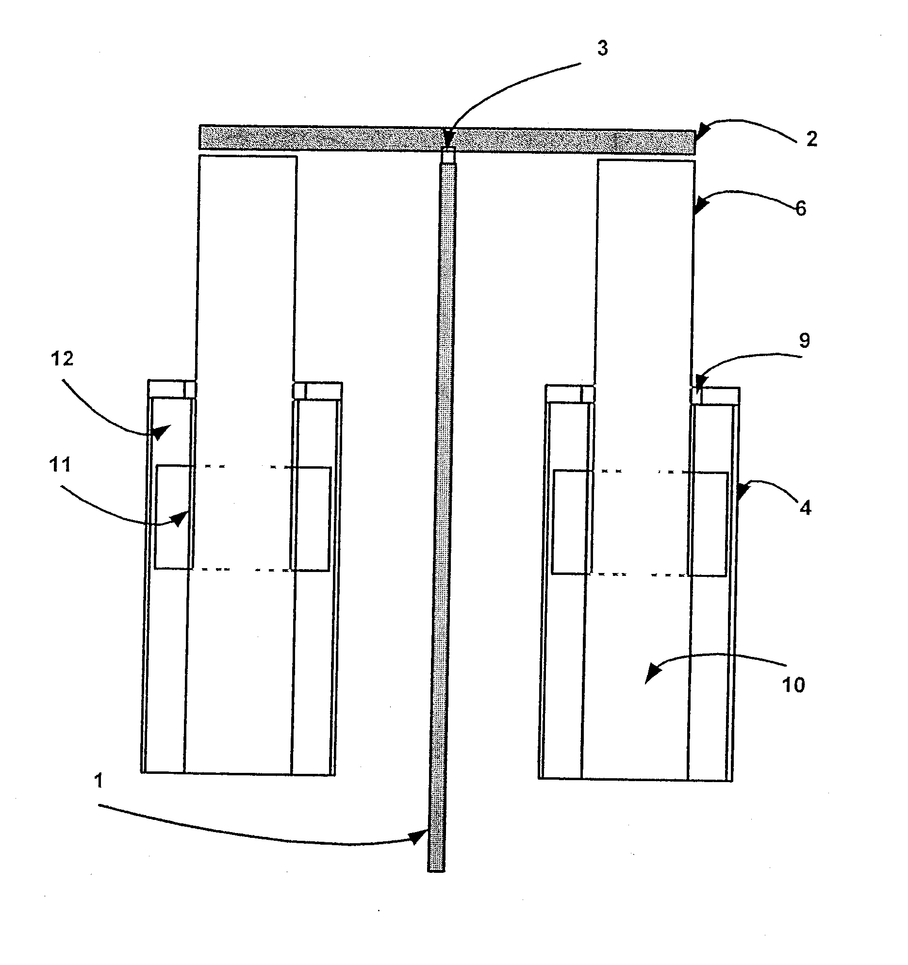
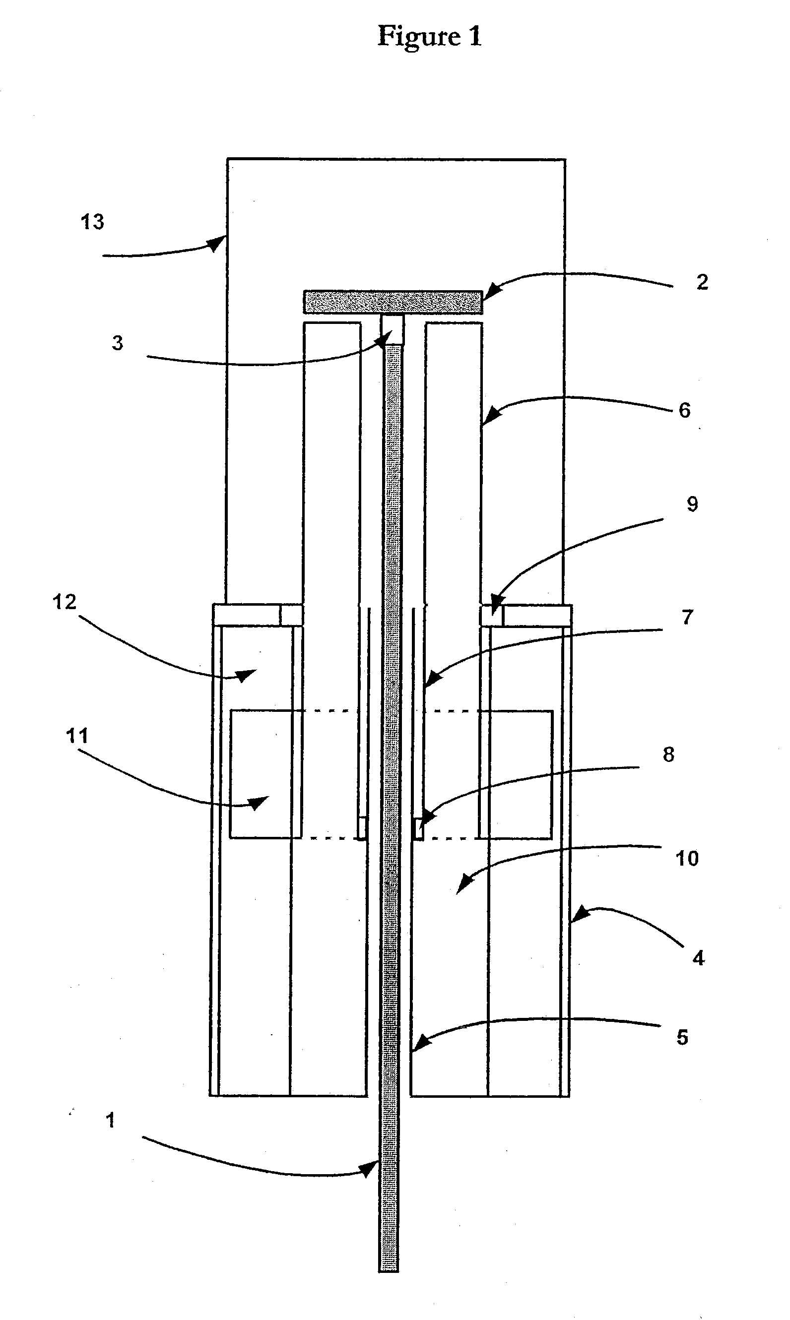
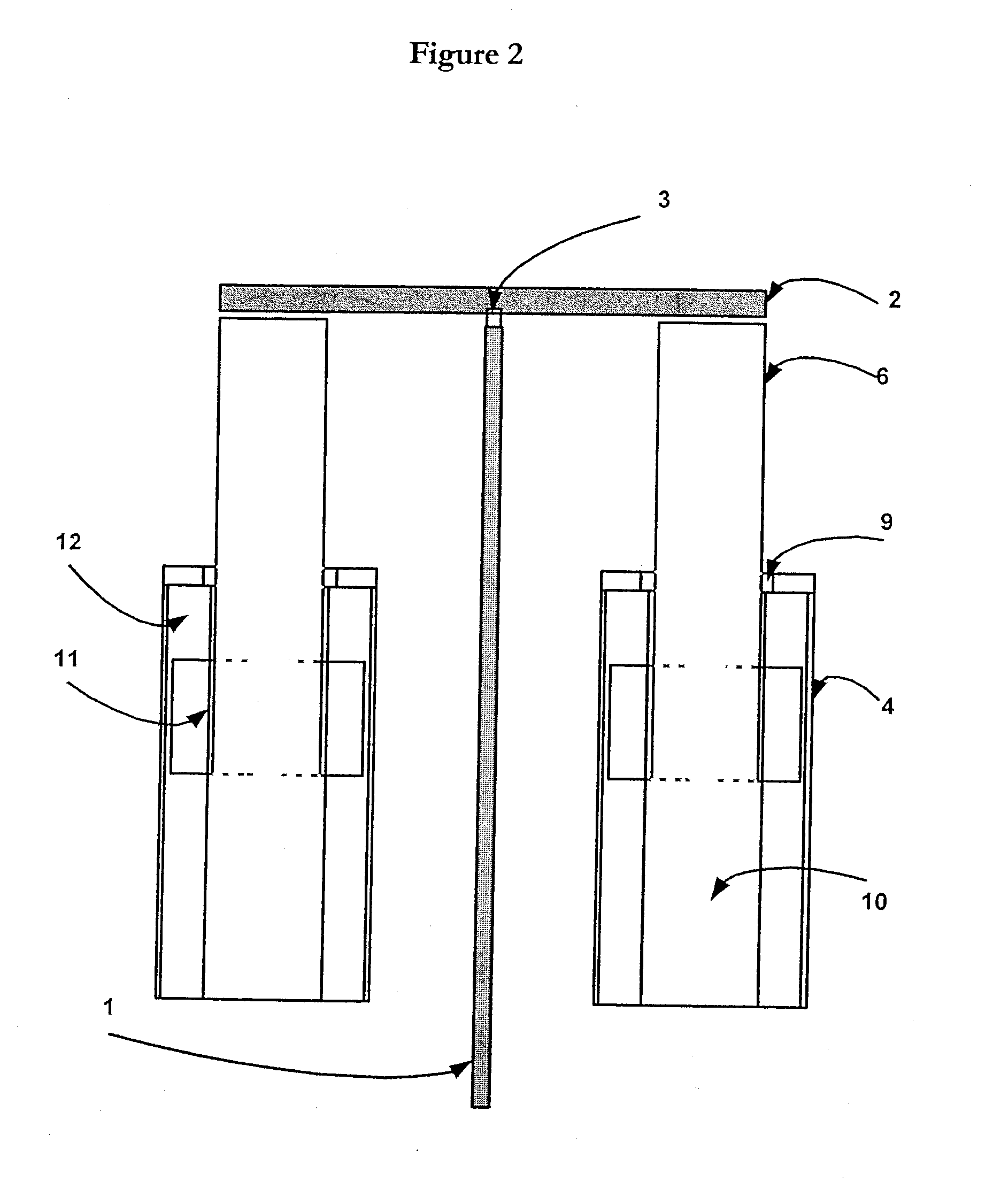
[0053]With reference to FIG. 1, shown is a diagrammatic vertical cross section of a basic cylindrical mechanism in which the polished rod of the pump string 1 is suspended from a disc 2 by means of a shackle or flexible coupling 3. The flexible coupling is necessary to accommodate the small tolerances in alignment that may exist or that may momentarily occur between the axis of the machine and the direction of the applied force. The rod 1 passes through a cylindrical channel or cavity in the body of the mechanism, the channel or cavity being bounded by the upper tube 7 and the lower tube 5. The interior of the mechanism is made gas-tight by means of the seal and bearing unit 8 between the coaxial tubes 5 and 7.

[0054]The rod string 1 is raised and lowered by means of the extendible cylinder 6 to which the disc 2 is affixed on its uppermost outer surface. The cylinder 6 extends variably from the body of the machine 4 through a second bearing and seal unit 9. The position of the cylind...


PUM


Abstract

The invention relates to electric linear motors and gas springs in reciprocating pumps for oil wells. By the use of this invention a simple, silent, compact and adaptable mechanism can be constructed to drive a wide range of such pumps. The mechanism will sense a variety of pumping conditions and react automatically thereto.

Description

TECHNICAL FIELD[0001]The present invention relates to a form of mechanism intended to drive a reciprocating pump to lift liquids from a deep well or borehole.BACKGROUND ART[0002]In a “jack pump” mechanism, a piston and non-return-valve unit at the base of the well or borehole (which may be several thousand metres deep) is generally connected to the drive mechanism at the surface by means of a long steel rod that, being assembled in sections and screwed together, is known as a rod string. The topmost section of that string—the section that emerges from the well through a pressure seal—necessarily has a higher surface finish and is known as the polished (or polish) rod. The polished rod is directly connected to the reciprocating mechanism that forms the invention described herein.[0003]It has long been known to construct such mechanisms in the form of an oscillating horizontal beam having a hammer-shaped end, over which is wrapped a chain or cable from which the pumping string is susp...

Claims


Application Information

Patent Timeline
Patent Type & Authority Applications(United States)
IPC IPC(8): F04B47/04F04B17/03
CPCE21B43/127F04B47/04F04B17/042F04B47/02E21B43/13E21B43/126
Inventor DENNE, PHILLIP
Owner CROSTEK MANAGEMENT CORP
Why Eureka
Try Eureka