Tio2-containing silica glass and optical member for lithography using the same

Active Publication Date: 2010-12-16
ASAHI GLASS CO LTD
View PDF7 Cites 14 Cited by
  • Summary
  • Abstract
  • Description
  • Claims
  • Application Information

AI Technical Summary

Benefits of technology

[0012]For achieving a high throughput of the exposure tool for EUVL, it is effective to raise the energy of EUV light used for exposure. In this case, the temperature of the member is likely to rise over the conventionally expected temperature. Specifically, the temperature of the member is likely to rise to

Problems solved by technology

Also, if a large dimensional change occurs due to a temperature rise from room temperature to a temperature at which the member is used in an exposure tool for EUVL, the pitch or shape of the above-mentioned pattern changes from the state at room temperature, and this is considered to make the optical design of the optical member complicated.
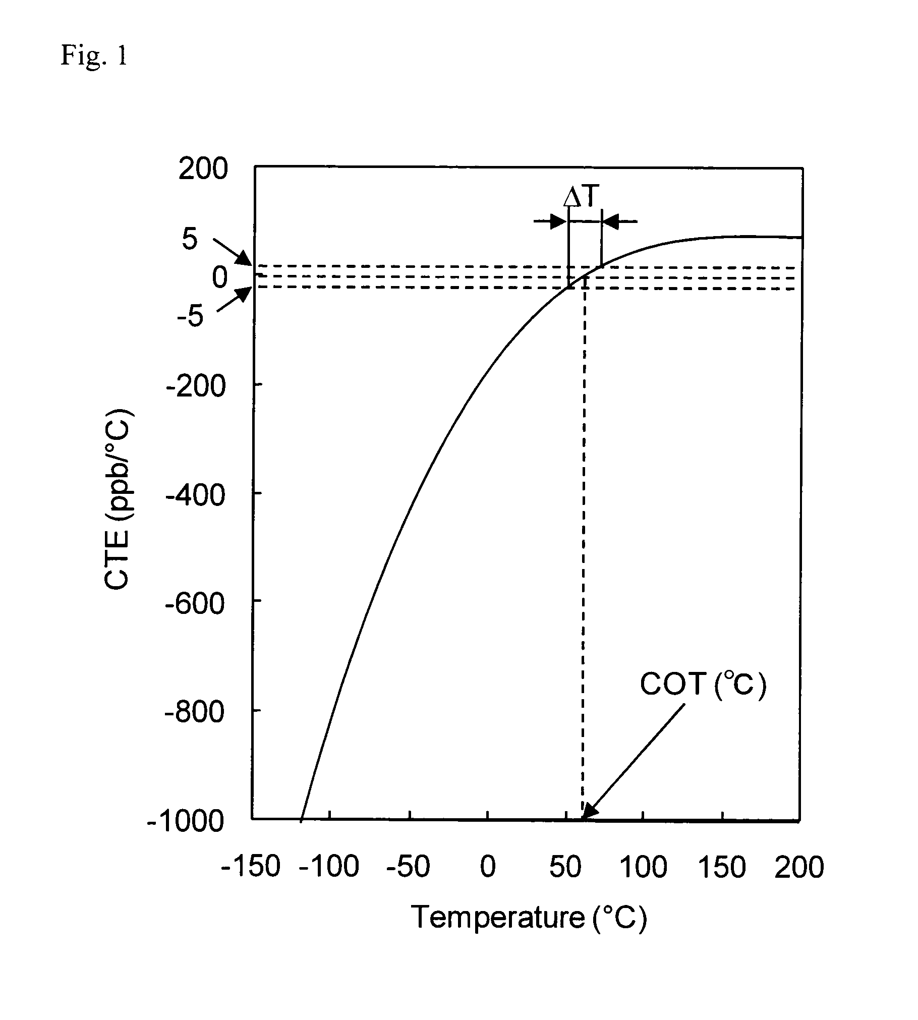
In the above-described conventional techniques, the temperature range allowing the coefficient of linear thermal expansion to become substantially zero is

Method used


Image

  • Tio2-containing silica glass and optical member for lithography using the same

Examples


example 1

[0067]TiO2—SiO2 glass fine particles obtained by gasifying each of TiCl4 and SiCla which are glass-forming materials for a TiO2—SiO2 glass, mixing these gases and subjecting the mixed gas to heat hydrolysis (flame hydrolysis) in oxyhydrogen flame is deposited and grown on a substrate to form a porous TiO2—SiO2 glass body (step (a)).

[0068]The obtained porous TiO2—SiO2 glass body is difficult to handle without any treatment and therefore, this porous glass body is kept in air at 1,200° C. for 6 hours together with the substrate and then separated from the substrate.

[0069]The porous TiO2—SiO2 glass body is set in an electric furnace capable of controlling the atmosphere. After reducing the pressure to 1,300 Pa at room temperature, water is charged into a glass-made bubbler, bubbling is performed with an He gas under a normal pressure at 80° C., and while introducing water vapor together with an He gas into the furnace, the glass body is kept in this atmosphere at 1,000° C. under normal...

example 2

[0074]A TiO2—SiO2 glass body is obtained in the same manner as in Example 1 except that in the step (a) of Example 1, the amount of TiCl4 supplied is slightly increased.

example 3

[0075]TiO2—SiO2 glass fine particles obtained by gasifying each of TiCl4 and SiCl4 which are glass-forming materials for a TiO2—SiO2 glass, mixing these gases and subjecting the mixed gas to heat hydrolysis (flame hydrolysis) in oxyhydrogen flame is deposited and grown on a substrate to form a porous TiO2—SiO2 glass body (step (a)).

[0076]The obtained porous TiO2—SiO2 glass body is difficult to handle without any treatment and therefore, this porous glass body is kept in air at 1,200° C. for 6 hours together with the substrate and then separated from the substrate.

[0077]The porous TiO2—SiO2 glass body is set in an electric furnace capable of controlling the atmosphere. After reducing the pressure to 1,300 Pa at room temperature, water is charged into a glass-made bubbler, bubbling is performed with an He gas under a normal pressure at 100° C., and while introducing water vapor together with an He gas into the furnace, the glass body is kept in this atmosphere at 1,000° C. under norma...


PUM

PropertyMeasurementUnit
Temperatureaaaaaaaaaa

Abstract

The present invention is to provide a TiO2—SiO2 glass whose coefficient of linear thermal expansion at the time of irradiating with high EUV energy light becomes substantially zero when used as an optical member of an exposure tool for EUVL. The present invention relates to a TiO2-containing silica glass, having a fictive temperature of 1,000° C. or lower, a OH concentration of 600 ppm or higher, a temperature at which the coefficient of linear thermal expansion becomes 0 ppb/° C. of from 40 to 110° C., and an average coefficient of linear thermal expansion in the temperature range of 20 to 100° C., of 50 ppb/° C. or lower.

Description

TECHNICAL FIELD[0001]The present invention relates to a TiO2-containing silica glass (hereinafter, in the context of the present invention, referred to as a TiO2—SiO2 glass). More specifically, the present invention relates to a TiO2—SiO2 glass that is used as an optical member of an exposure tool for EUV lithography. Incidentally, EUV (extreme ultraviolet) light as used in the present invention indicates light with a wavelength band in a soft X-ray region or a vacuum ultraviolet region, and this is specifically light at a wavelength of approximately from 0.2 to 100 nm.BACKGROUND ART[0002]In the photolithography technology, an exposure tool for manufacturing an integrated circuit by transferring a fine circuit pattern onto a wafer has hitherto been widely utilized. With the trend toward a higher degree of integration and a higher function of an integrated circuit, the refinement of the integrated circuit is advancing. The exposure tool is hence required to form a circuit pattern ima...

Claims


Application Information

Patent Timeline
IPC IPC(8): C03C3/06
CPCC03B19/1453C03B2201/23C03B2201/42C03C2203/54C03C2201/23C03C2203/44C03C2203/52C03C3/06C03C4/0085H01L21/0275
Inventor KOIKE, AKIOIWAHASHI, YASUTOMIKIKUGAWA, SHINYA
Owner ASAHI GLASS CO LTD
Why Eureka
Try Eureka