Multiple Fuel Circuits for Syngas/NG DLN in a Premixed Nozzle

a fuel circuit and premixing nozzle technology, applied in the direction of machines/engines, mechanical equipment, light and heating equipment, etc., can solve the problems of low emission combustors, degradation of emissions performance, overheating and damage to the premixing section,

Inactive Publication Date: 2010-12-23
GENERAL ELECTRIC CO
View PDF6 Cites 27 Cited by
  • Summary
  • Abstract
  • Description
  • Claims
  • Application Information

AI Technical Summary

Benefits of technology

[0012]In an exemplary embodiment, a fuel/air premixer is for use in a burner in a combustion system of an industrial gas turbine. The fuel air premixer includes an air inlet, at least two fuel inlets, a corresponding at least two fuel sources coupled with the at least two fuel inlets, and an annular mixing passage. The fuel/air premixer mixes fuel and air in the annular mixing passage for injection into a combustor reaction zone. A swozzle assembly is disposed downstream of the air inlet. The swozzle assembly may include a plurality of turning vanes positioned to impart swirl to incoming air. Each of the turning vanes includes an internal fuel flow passage communicating with at least one of the fuel inlets. At least some of the fuel i

Problems solved by technology

There are several problems associated with dry low emissions combustors operating with lean premixing of fuel and air.
The consequences of combustion in the premixing section are degradation of emissions performance and/or overheating and damage to the premixing section, which is typically not designed to withstand the heat of combustion.
Therefore, a problem to be solved is to prevent flashback or auto-ignition resulting in combustion within the premixer.
This can result in failure to meet NOx emissions objectives depending upon the combination of temperature and residence time.
If regions in the flow field exist where the fuel/air mixture strength is significantly leaner than average, then quenching may occur with failure to oxidize hydrocarbons and/or carbon monoxide to equilibrium levels.
This can result in failure to meet carbon monoxide (CO) and/or unburned hydrocarbon (UHC) emissions objectives.
As a consequence, lean premixing combustors tend to be less stable than more conventional diffusion flame combustors, and high level combustion driven dynamic pressure activity often results.
This high level dynamic pressure activity can have adverse consequences such as combustor and turbine hardware damage due to wear or fatigue, flashback or blow out.
Thus, yet another problem to be so

Method used


Image

  • Multiple Fuel Circuits for Syngas/NG DLN in a Premixed Nozzle
  • Multiple Fuel Circuits for Syngas/NG DLN in a Premixed Nozzle
  • Multiple Fuel Circuits for Syngas/NG DLN in a Premixed Nozzle

Examples


Embodiment Construction

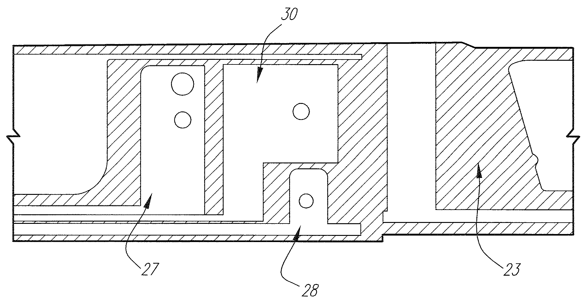
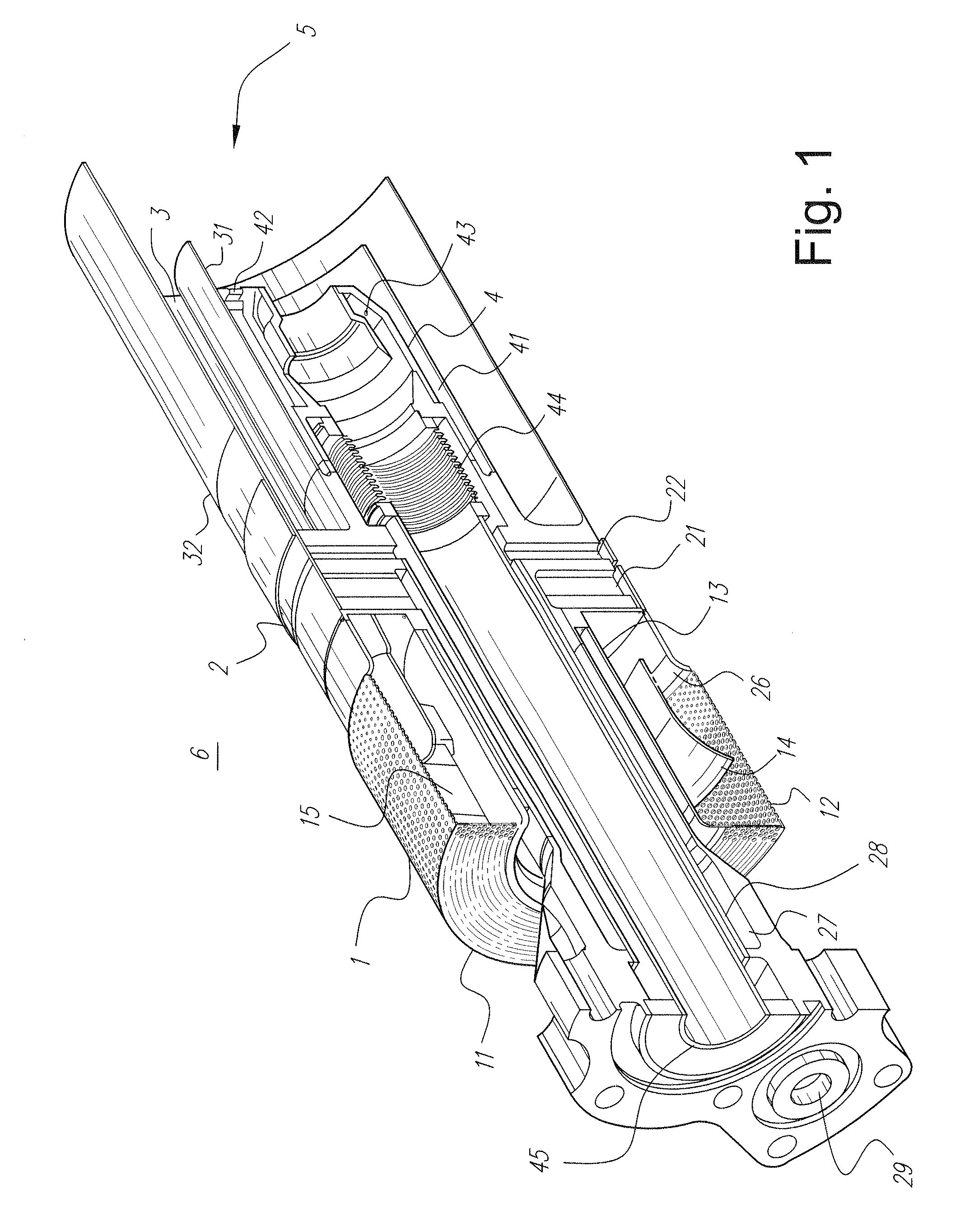
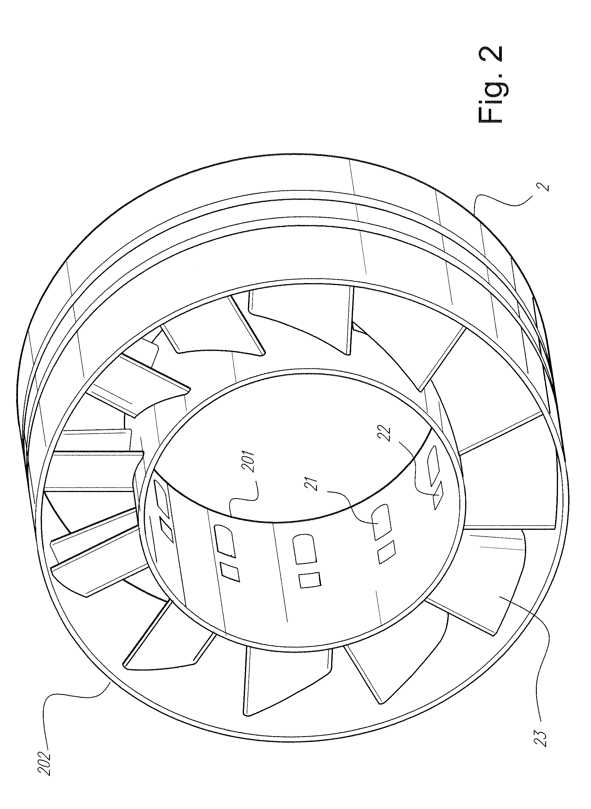
[0019]FIG. 1 is a cross-section through the burner described in U.S. Pat. No. 6,438,961, and FIGS. 2 and 3 show details of the air swirler assembly with fuel injection through the turning vanes or swozzle. In practice, an air atomized liquid fuel nozzle would be installed in the center of the burner assembly to provide dual fuel capability; however, this liquid fuel nozzle assembly does not form part of the invention and has been omitted from the illustrations for clarity. The burner assembly is divided into four regions by function including an inlet flow conditioner 1, an air swirler assembly with natural gas fuel injection (referred to as a swozzle assembly) 2, an annular fuel air mixing passage 3, and a central diffusion flame natural gas fuel nozzle assembly 4.

[0020]Air enters the burner from a high pressure plenum 6, which surrounds the entire assembly except the discharge end, which enters the combustor reaction zone 5. Most of the air for combustion enters the premixer via t...


PUM


Abstract

A fuel/air premixer for use in a burner in a combustion system of an industrial gas turbine includes an air inlet, a fixed nozzle geometry, and an annular mixing passage. The fuel/air premixer mixes fuel and air in the annular mixing passage for injection into a combustor reaction zone. A plurality of fuel sources are connected with the fixed nozzle geometry, and each of the fuel sources is cooperable with the fixed nozzle geometry to effect multiple fuel flow variations including variations in fuel type, fuel blend, volumetric flow, and pressure ratios.

Description

BACKGROUND OF THE INVENTION[0001]The present invention relates to heavy duty industrial gas turbines and, in particular, to a burner for an industrial gas turbine including a fuel / air premixer enabling mixtures of multiple gas streams for desired performance such as fuel mixing for emissions, flame holding robustness, and control of combustion oscillations.[0002]Gas turbine manufacturers are currently involved in research and engineering programs to produce new gas turbines that will operate at high efficiency without producing undesirable air polluting emissions. The primary air polluting emissions usually produced by gas turbines burning conventional hydrocarbon fuels are oxides of nitrogen, carbon monoxide, and unburned hydrocarbons. It is well known in the art that oxidation of molecular nitrogen in air breathing engines is highly dependent upon the maximum hot gas temperature in the combustion system reaction zone. The rate of chemical reactions forming oxides of nitrogen (NOx)...

Claims


Application Information

Patent Timeline
IPC IPC(8): F02C7/22
CPCF23R3/36F23R3/286
Inventor INTILE, JOHN CHARLES
Owner GENERAL ELECTRIC CO
Why Eureka
Try Eureka