Wireless laser power transmitter

US20100320362A1Active Publication Date: 2010-12-23WI CHARGE

Image

  • Wireless laser power transmitter
  • Wireless laser power transmitter
  • Wireless laser power transmitter

Examples


Embodiment Construction

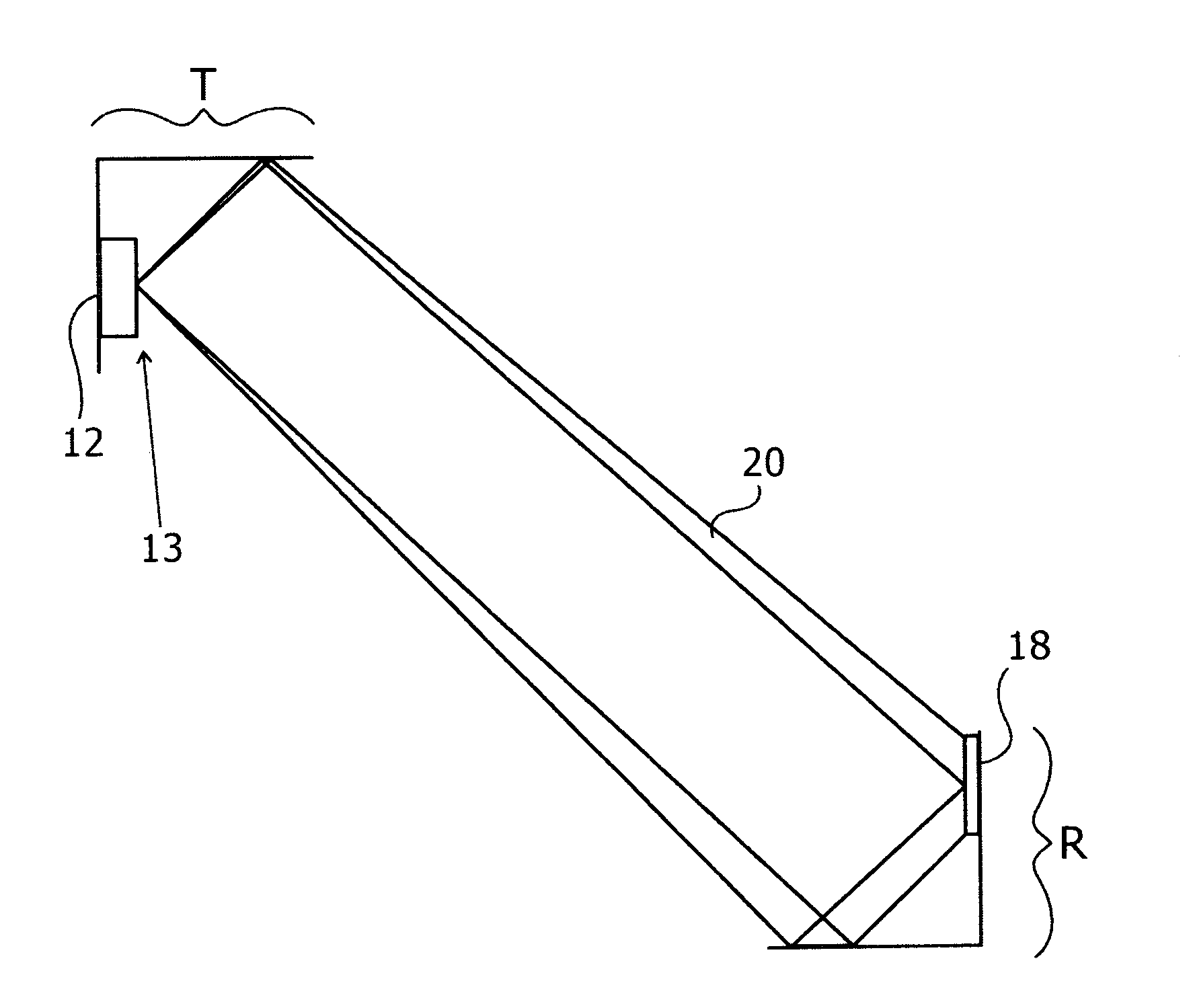
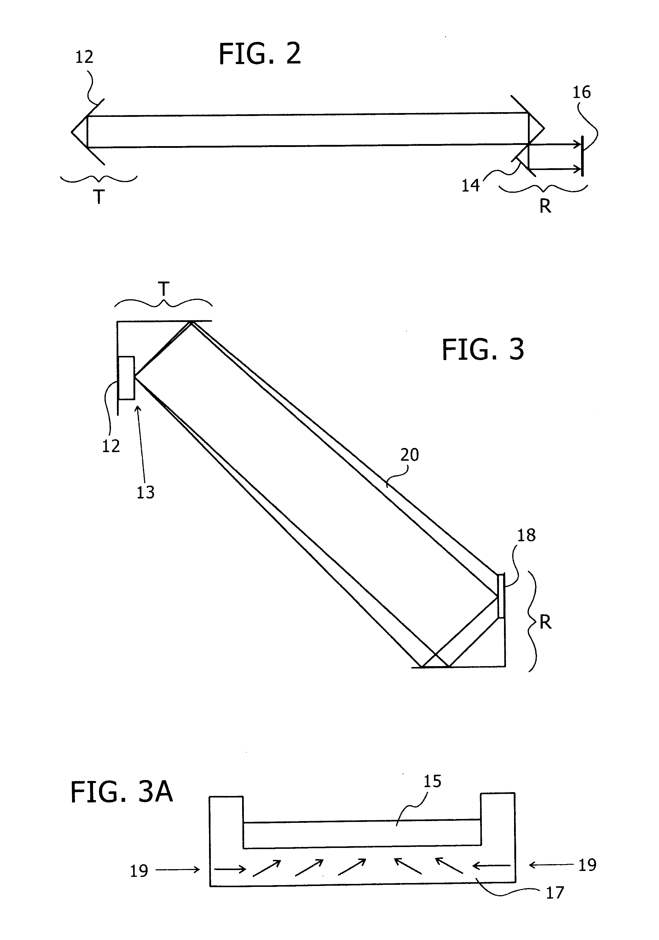
[0088]Reference is now made to FIG. 2, which illustrates schematically an exemplary power transmitting system comprising an electrically powered transmitter T, and a receiver R, which allows extraction of electric energy, in order to power, for instance, a mobile electronic device. The transmitter should be mounted at a safe location out of reach of possible human contact, such as on the ceiling of a room or connected to a lighting fitting. The position should be such that the transmitter has a line of sight to as much of the room's volume as possible. Suitable positions may be to embed the transmitter within a ceiling lamp, within a television set or within a speaker unit, one approach to achieve that would be to add a standard lamp connection to the transmitter so that it can connect to a standard lamp fitting.

[0089]T and R form a laser resonator, in which significant power circulates in the form of a laser beam(s), which may advantageously be in the infra-red. Since this arrangem...


PUM

PropertyMeasurementUnit
Angleaaaaaaaaaa
Angleaaaaaaaaaa
Temperatureaaaaaaaaaa

Abstract

An optical power beam transmission systems, with a directional light transmitter and receiver. The transmitter contains an amplifying laser medium, and this together with a retroreflector in the receiver, forms a laser resonator. When lasing sets in, the receiver can extract optical power through an output coupler and convert it to electrical power. The gain medium may be a disc having a thickness substantially smaller than its lateral dimensions. The laser resonator is operated as a stable resonator to ensure safe operation. This is achieved by use of an adaptive optical element, for reducing the diameter of the energy beam impinging on the gain medium, thereby increasing the overlap between the energy beam and the gain medium. As the transmitter-receiver distance is changed, such as by movement of the receiver, the adaptive optical element focal length changes to ensure that the cavity remains within its stability zone.

Description

FIELD OF THE INVENTION[0001]The present invention relates to the field of the wireless transmission of power to a remote device over free space, especially by means of a laser-like system.BACKGROUND OF THE INVENTION[0002]In recent years mobile devices have found widespread popular use. In many cases, these devices use a battery to provide electric power; in other cases they draw their power from another device such as a computer via an electrical cable, through a USB port for example. One of the most common drawbacks of such devices is the need for recharging the battery, in the case of a rechargeable battery, or replacement of the battery in the case of a non-rechargeable battery, or the inconvenience of requiring a cable connection. It would be desirable if such devices were able to receive their power, or at least part of it, wirelessly from a remote source, thus reducing the need for recharging cycles or change of batteries, while not limiting the device to be bound to a fixed l...

Claims


Application Information

Patent Timeline
23 Dec 2010
Publication
US20100320362A1
IPC
H02J17/00
CPC
H01S3/083; H01S5/041; H01S5/14; H04B10/807; H01S5/10; H04B10/114; H01S3/0805; H01S3/08072
Inventors
ALPERT, ORTAL; PASCHOTTA, RUDIGER