

Touch sensor, display and electronic unit
- Summary
- Abstract
- Description
- Claims
- Application Information
AI Technical Summary
Benefits of technology
Problems solved by technology
Method used
Image

Examples
first embodiment (
2. First Embodiment (Example of a method of removing external noise with use of three or more filters allowing a fundamental frequency and two or more harmonic frequencies of a detection drive frequency to pass therethrough, respectively)
second embodiment (
3. Second Embodiment (Example in which a transverse electric mode liquid crystal element is used as a display element)
application examples (
4. Application Examples (Application examples of a display with a touch sensor to electronic units)
5. Other modifications
[0050]Basic Principle of Touch Detection System
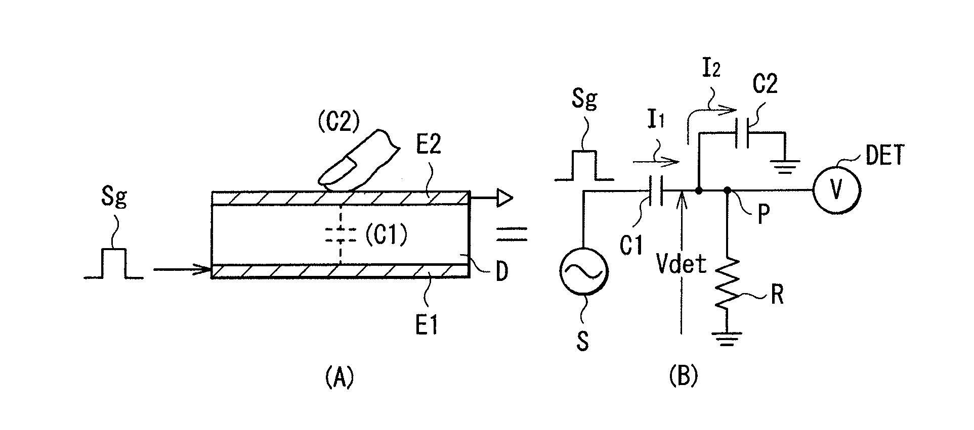
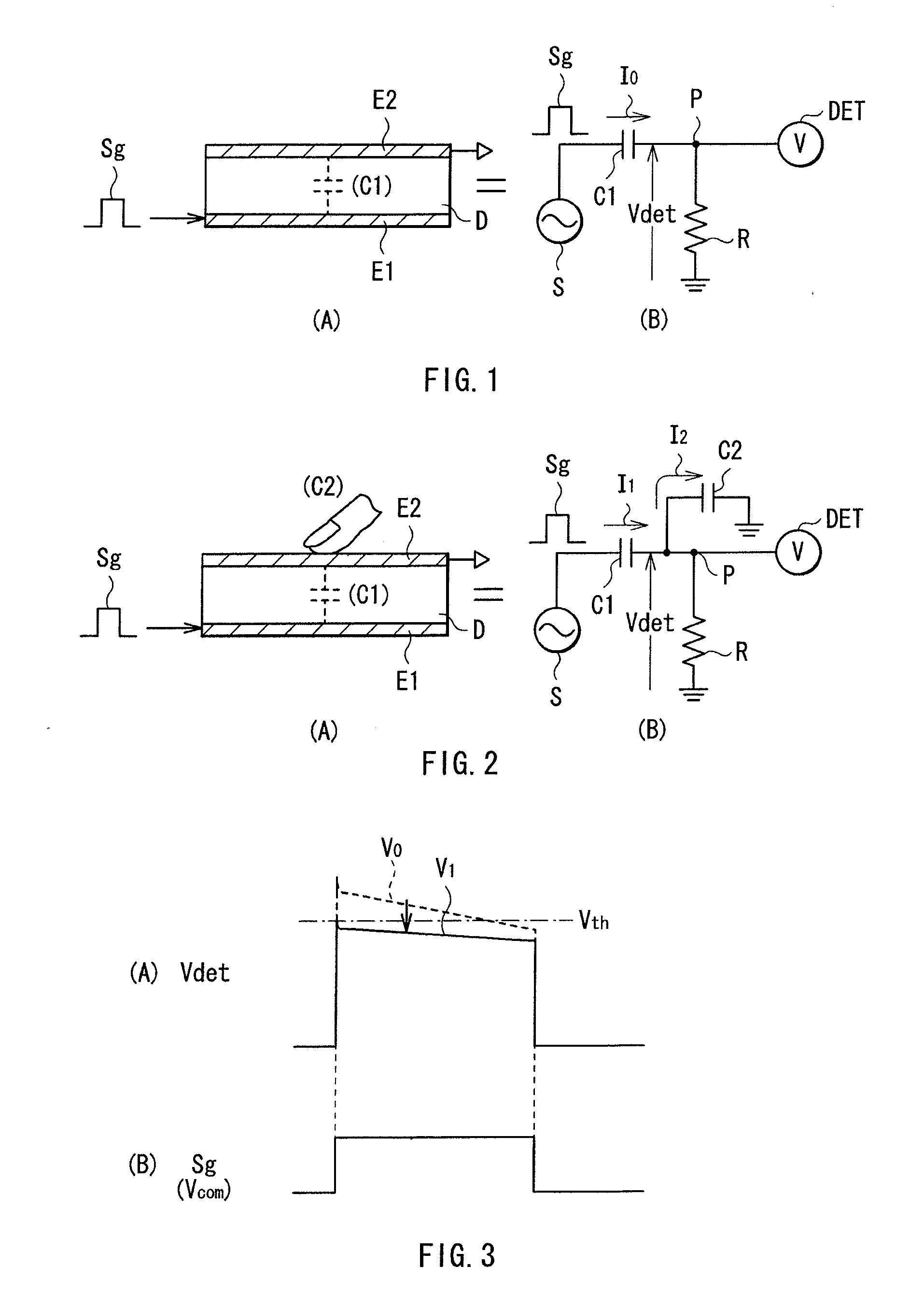
[0051]First, referring to FIGS. 1 to 3, a basic principle of a touch detection system in a display with a touch sensor of the present invention will be described below. The touch detection system is embodied as a capacitive type touch sensor, and, for example, as illustrated in a part A in FIG. 1, the touch detection system has a configuration in which a capacitive element is configured of a pair of electrodes (a drive electrode E1 and a detection electrode E2) arranged to face each other with a dielectric D in between. This configuration is illustrated as an equivalent circuit illustrated in a part B in FIG. 1. A capacitive element C1 is configured of the drive electrode E1, the detection electrode E2 and the dielectric D. In the capacitive element C1, one end thereof is connected to an AC signal source (a drive sign...
PUM
 Abstract
Description
Claims
Application Information