
Methods and Apparatus for Fabricating Porous Three-Dimensional Tubular Scaffolds

a three-dimensional tubular and scaffold technology, applied in envelope/bag making machinery, paper/cardboard containers, packaging foodstuffs, etc., can solve the problems of inefficient tubular porous structure fabrication system, xyz, time-consuming two-step process, etc., to achieve easy control or manipulation of pores, pore size, structure, and mechanical properties

Active Publication Date: 2010-12-30
BEIJING ADVANCED MEDICAL TECH
View PDF15 Cites 35 Cited by
  • Summary
  • Abstract
  • Description
  • Claims
  • Application Information

AI Technical Summary

Benefits of technology

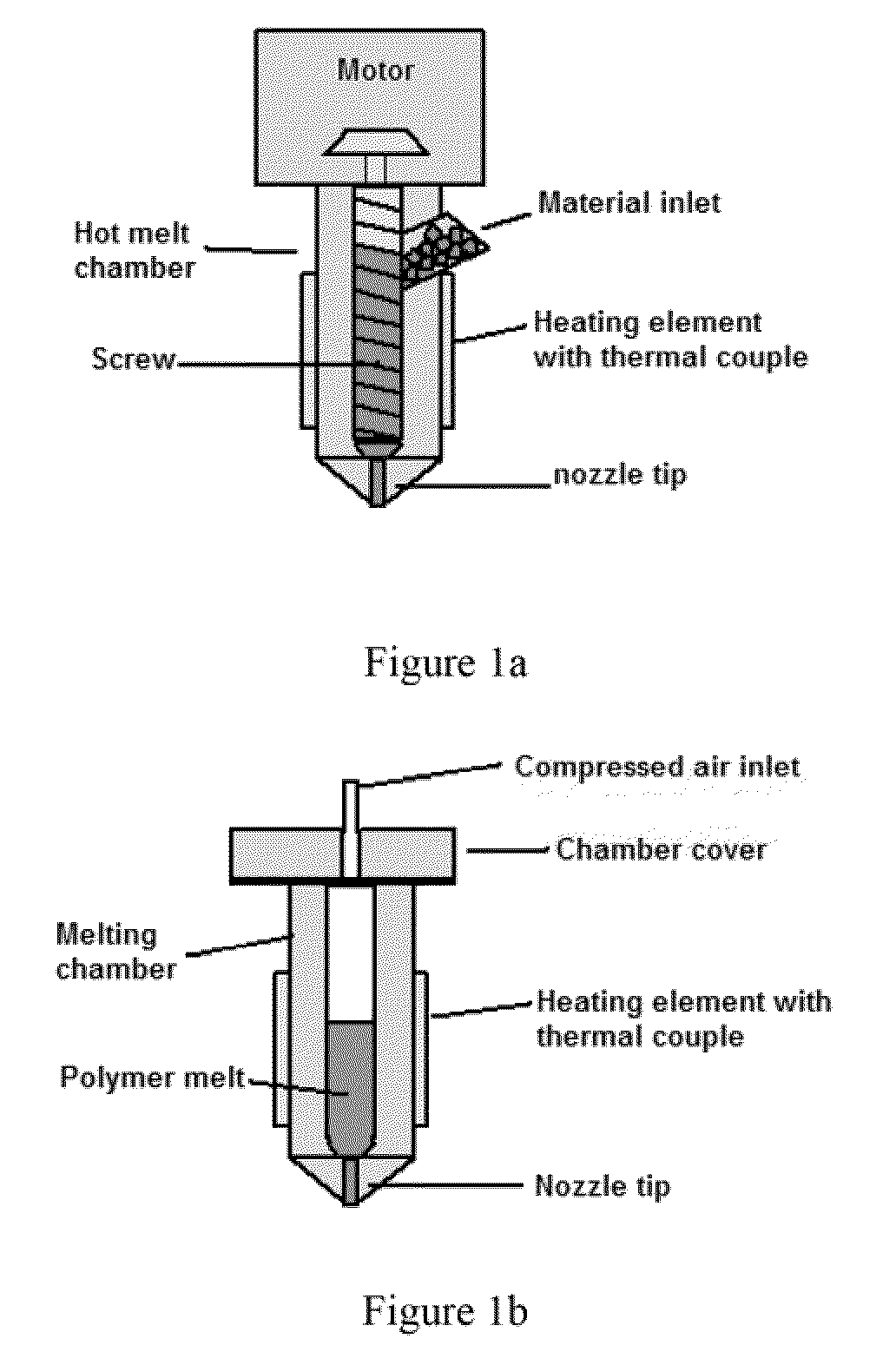
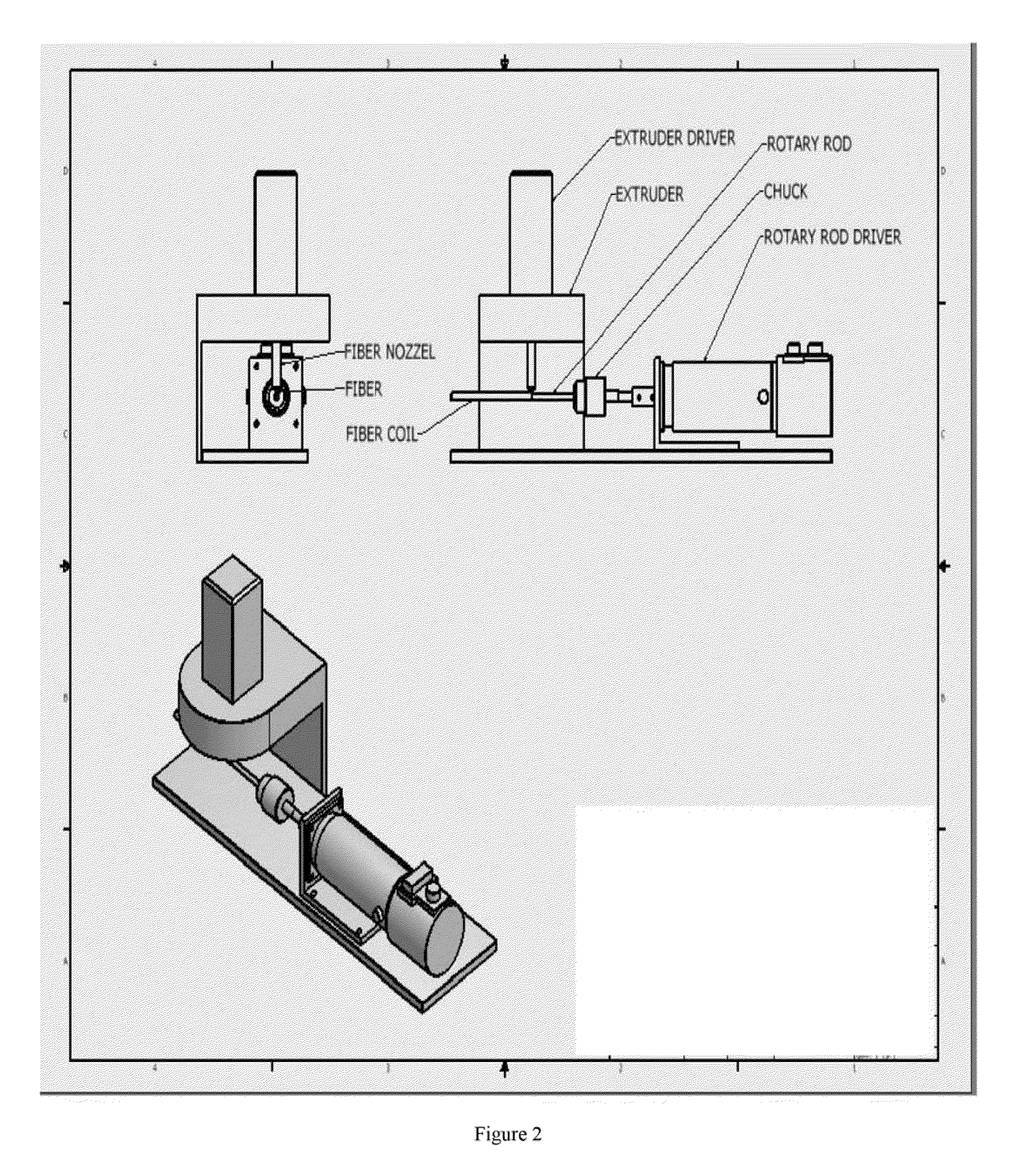
[0012]It is therefore an object of the present invention to provide methods to fabricate porous polymeric three-dimensional (3D) tubular scaffolds whereby the porosity, pore size, structure, and mechanical properties can be easily controlled or manipulated.
[0013]It is a further object to the present invention to provide a 4 axis RP system in which the 4th axis is a computer controlled rotation shaft added to an xyz position system. In preferred embodiments, the 4 axis RP system also has a material delivery system that directly deposits polymer material in a hot melt filament form or a viscous solution filament form. The deposited filament adheres to the surface of the rotation shaft or bonds to previously extruded filaments that are already attached to the rotation shaft. In addition, preferred embodiments allow for the fiber diameter to be changed by either varying the rotation speed of the 4th axis where the polymer filament is attached, or by varying the XY axis traveling speed, similar to a hot melt drawing process. This system is particularly suitable for making 3D tubular scaffolds with complicated micro-porous structures.

Problems solved by technology

However, the current RP systems have only three axis (XYZ) and are not efficient systems for fabricating tubular porous structures.
However, in this fabrication method, a polymer tube has to be made first, followed by laser cutting.
Overall, this is a time consuming two-step process.
Also, most of the polymer material is removed or wasted, particularly in the case of fabrication of a highly porous polymer stent.
This fabrication process can be expensive as medical grade polymer materials are typically expensive.
Further, the removal or the evaporation of the polymer by laser beam heating causes toxic gas emission, resulting in air pollution.

Method used


Image

  • Methods and Apparatus for Fabricating Porous Three-Dimensional Tubular Scaffolds
  • Methods and Apparatus for Fabricating Porous Three-Dimensional Tubular Scaffolds
  • Methods and Apparatus for Fabricating Porous Three-Dimensional Tubular Scaffolds

Examples


Embodiment Construction

[0027]In the 4 axis RP system of the present invention, the 4th axis is a computer controlled rotation shaft added to an xyz position system. The 4 axis RP system also has a material delivery system that directly deposits polymer material in a hot melt filament form or a viscous solution filament form. The deposited filament adheres to the surface of the rotation shaft or bonds to previously extruded filaments that already attached to the rotation shaft, therefore eliminating the need to use glue or controlled heating, as previously described in, e.g. US patent application (US 20030211130A1 by Sanders et al). In addition, the fiber diameter can be changed by either varying the rotation speed of the 4th axis where the polymer filament is attached, or by varying the XY axis traveling speed, similar to a hot melt drawing process. This system is particularly suitable for making 3D tubular scaffolds with complicated micro-porous structures.

[0028]3D tubular scaffolds made by the 4 axis RP...


PUM

PropertyMeasurementUnit
Pore sizeaaaaaaaaaa
Temperatureaaaaaaaaaa
Therapeuticaaaaaaaaaa

Abstract

Disclosed herein are three-dimensional porous tubular scaffolds for cardiovascular, periphery vascular, nerve conduit, intestines, bile conduct, urinary tract, and bone repair / reconstruction applications, and methods and apparatus for making the same.

Description

RELATED APPLICATIONS[0001]This application claims priority to U.S. Provisional Application No. 61 / 220,424, filed Jun. 25, 2009, the content of which is hereby incorporated by reference in its entirety.BACKGROUND OF THE INVENTION[0002]Regeneration of cellular tissue and organs is a rapidly growing field. Obstacles commonly found with conventional transplantation, such as donor tissue / organ shortage and host rejection, may be overcome by enabling the host to utilize his or her own cells to regenerate cellular tissue, repair a damaged nerve or blood vessel, etc.[0003]One important approach towards creating engineered tissue is Tissue Engineering, which uses a combination of a three-dimensional (3D) scaffold, progenitor cells and biological factors to “grow” a living tissue or organ. A 3D scaffold provides a structure for the cells to adhere to during their regeneration process, thereby guiding the cells into the size and shape of the desired structure. In this tissue regeneration proce...

Claims


Application Information

Patent Timeline
IPC IPC(8): A61F2/00A61P43/00A61P17/02B05C5/00B05D1/00B32B1/08B29C48/365
CPCA61F2/07A61F2/91B05B13/0442B05C5/0216B29C47/0014B29C47/36Y10T428/13B29C55/22B29D23/001B29L2023/007B29C47/38Y10T428/1362B29C53/60B29C48/05B29C48/395B33Y30/00B29C48/485A61P17/02A61P43/00B29C48/365
Inventor LIU, QINGWANG, ZONGSENLAU, WING K.
Owner BEIJING ADVANCED MEDICAL TECH
Learn More