Thin film battery and method of connecting electrode terminal of thin film battery

a thin film battery and electrode terminal technology, applied in the field of thin film batteries, can solve the problems of difficulty in connecting the cath the anode current collector pattern to an external device, etc., and achieve the effect of preventing or reducing thermal damage to the thin film battery and high bonding for

Inactive Publication Date: 2010-12-30
GSNANOTECH
View PDF7 Cites 42 Cited by
  • Summary
  • Abstract
  • Description
  • Claims
  • Application Information

AI Technical Summary

Benefits of technology

[0009]An aspect of the present invention provides a thin film battery in which a bonding force between electrodes terminals may be enhanced and a thermal damage due to bonding may be reduced.
[0010]Another aspect of the present invention also provides a method of connecting electrode terminals of a thin film battery that may increase a bonding force, and may reduce a thermal damage to a thin film battery when connecting electrode terminals of the thin film battery.
[0015]According to embodiments of the present invention, it is possible to simply connect electrode terminals of a thin film battery to have a high bonding force. Also, when connecting the electrode terminals, although a thermal process may be omitted or not be omitted, heat may be locally transferred to the thin film battery. Accordingly, it is possible to prevent or reduce a thermal damage to the thin film battery.

Problems solved by technology

However, in the case of a thin film battery, a cathode current collector pattern and an anode current collector pattern are formed in a thin film having a thickness measured in thousands of Å. Thus, it is difficult to connect the cathode current collector pattern and the anode current collector pattern to an external device.
However, the above schemes may cause damage to the thin film battery due to an external impact, coming-off of an under-layer, and a thermal transfer, and may also need to continuously maintain a predetermined pressure.

Method used


Image

  • Thin film battery and method of connecting electrode terminal of thin film battery
  • Thin film battery and method of connecting electrode terminal of thin film battery
  • Thin film battery and method of connecting electrode terminal of thin film battery

Examples


example 1

[0061]A mica film having a thickness of 50 μm was used as a base substrate, and Pt was direct current (DC) sputtered to have a thickness of about 300 nm as a cathode current collector pattern. To increase an adhesive property with the base substrate, Ti was deposited between Pt and the base substrate to have a thickness of about 150 nm. LiCoO2 target was used as a cathode active material and was magnetron sputtered by applying a DC / radio frequency (RF) hybridization power in a thickness of about 3 nm in an atmosphere of about 10 to 20 mTorr of argon / oxygen mixture gas. For crystallization of an anode, a rapid heat-treatment process was performed in a process condition not destroying a vacuum state. A solid electrolyte layer thin film was formed by depositing LiPON electrolyte layer with a thickness of about 1.5 nm, the LiPON electrolyte layer was a form that oxygen within Li3PO4 is partially substituted to nitride by using Li3PO4 target and by RF magnetron sputtering in a pure nitro...

example 2

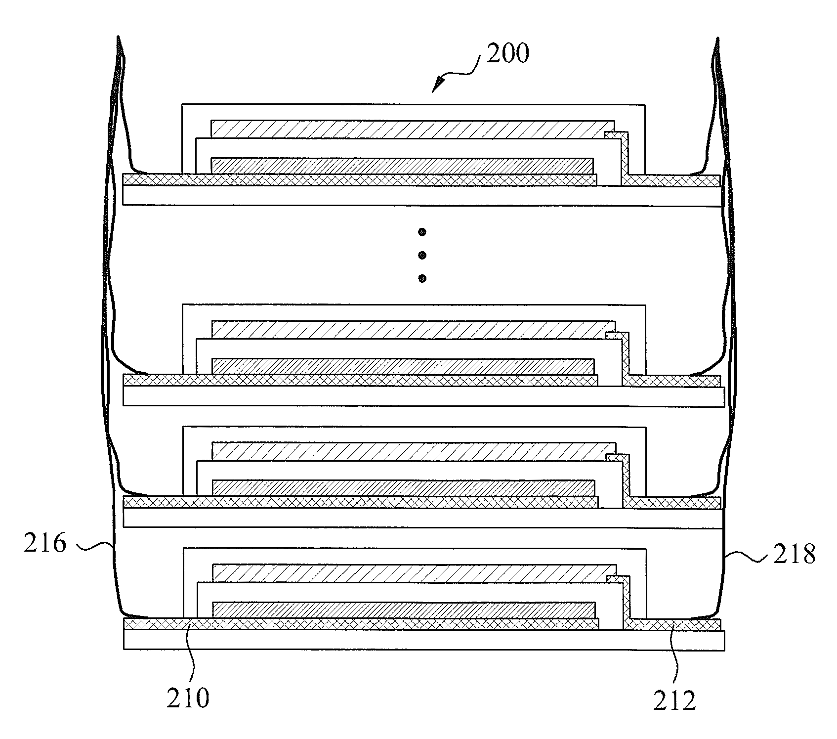
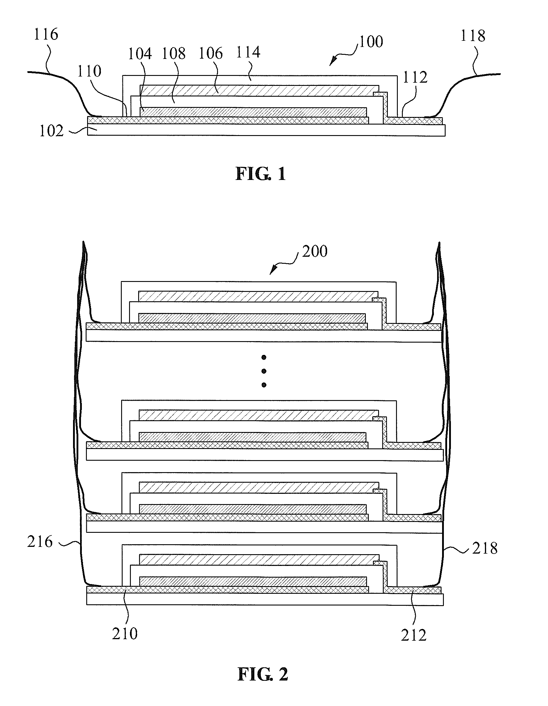
[0063]Seven unit cells, each connected with electrode terminals as same as Example 1, were manufactured. A thin film battery was manufacturing by disposing the seven unit cells. Next, after connecting cathode terminals to each other and connecting anode terminals to each other, each of the connected cathode terminals and the anode terminals was integrated using a spot welding.

[0064]To verify whether the thin film battery connected with each unit cell was appropriately operating, a capacity of the unit cell manufactured according to Example 1 was compared with a capacity of the thin film battery where the seven unit cells were disposed according to Example 2. A result of comparison is shown in FIG. 5.

[0065]Referring to FIG. 5, when a discharge was made based on about 1 C rate (100 μA), the capacity of the unit cell manufactured according to Example 1 was on average about 100 μAh. When the discharge was made based on about 1 C rate (700 μA), the capacity of the thin film battery where...


PUM

PropertyMeasurementUnit
thicknessaaaaaaaaaa
thicknessaaaaaaaaaa
thicknessaaaaaaaaaa

Abstract

Provided is a thin film battery, including: a base substrate; a cathode current collector pattern and an anode current collector pattern being formed on the base substrate and being electrically separate from each other; a cathode terminal and an anode terminal being directly bonded with the cathode current collector pattern and the anode current collector pattern; a cathode and an anode being disposed on the cathode current collector pattern and the anode current collector pattern; and an electrolyte layer being disposed between the cathode and the anode.

Description

CROSS-REFERENCE TO RELATED APPLICATION[0001]This application claims the benefit under 35 U.S.C. §119 of Korean Patent Application No. 10-2009-0058990, filed on Jun. 30, 2009, which is hereby incorporated by reference in its entirety.BACKGROUND[0002]1. Field of the Invention[0003]The present invention relates to a battery, and more particularly, to a thin film battery and a method of connecting electrode terminals of the thin film battery.[0004]2. Description of the Related Art[0005]In the case of a general bulk-type lithium battery, that is, a lithium ion battery or a lithium polymer battery, an electrode tap connection may use welding between an aluminum tap and an aluminum foil with respect to a cathode and may use ultrasonic or rivet welding between a nickel tap and a copper foil with respect to an anode. Through this, electrode terminals may be formed.[0006]However, in the case of a thin film battery, a cathode current collector pattern and an anode current collector pattern are...

Claims


Application Information

Patent Timeline
Patent Type & Authority Applications(United States)
IPC IPC(8): H01M10/28H01M4/00H01M10/26H01M50/186H01M50/191
CPCH01M2/08H01M2/22H01M4/661H01M10/0436Y10T29/49108H01M10/0562H01M10/0585Y02E60/122H01M10/052Y02E60/10H01M50/528Y02P70/50H01M50/186H01M50/191H01M10/38H01M4/64
Inventor NAM, SANG CHEOLPARK, HO YOUNGLIM, YOUNG CHANGLEE, KI CHANGJUNG, YOUNG KYUN
Owner GSNANOTECH
Why Eureka
Try Eureka