

Method for prolonging a catalyst's life during hydrofluorination
- Summary
- Abstract
- Description
- Claims
- Application Information
AI Technical Summary
Benefits of technology
Problems solved by technology
Method used
Image

Examples
example 1
[0057]A continuous liquid phase fluorination of the 2-chloro-3,3,3-trifluoropropene (HCFO-1233xf)+HF→2-chloro-1,1,1,2-tetrafluoropropane (HCFC-244bb) is conducted, using as fluorination catalyst fluorinated SbCl5.
[0058]Prior to the reaction, the 2-chloro-3,3,3-trifluoropropene (HCFO-1233xf) raw material [which had previously been prepared by vapor phase hydrofluorination reaction from 1,1,2,3,-tetrachloropropene (HCC-1230xa)] is distilled in a multi-stage distillation column under pressure to a purity in excess of 99%.
[0059]2230 grams of mixed antimony chlorides (5 moles SbCl5 per 1 mole SbCl3) are added into a Teflon™-lined liquid phase reactor (Teflon is a trademark of E.I. duPont de Nemours & Co) equipped with a catalyst stripper, 2-inch ID (inside diameter) packed column and with a condenser whose function is to return entrained catalyst, some of the unreacted HF and some of the unreacted HCFO-1233xf to the reactor when the system is running in continuous reaction mode. The reac...
example 2
[0061]This example illustrates the continuous vapor phase fluorination reaction of 1,1,2,3-tetrachloropropene (TCP)+3HF→2-chloro-3,3,3-trifluoropropene (HCFO-1233xf)+3HCl. The fluorination catalyst for the experiment was fluorinated Cr2O3.
[0062]A continuous vapor phase fluorination reaction system consisting of N2, HF, and organic feed systems, feed vaporizer, superheater. 4″ ID Monel reactor, acid scrubber, drier, and product collection system was used to study the reaction. The reactor was loaded with 9415.2 grams of pretreated Cr2O3 catalyst which equates to about 6.5 liters of catalyst. The reactor was then heated to a reaction temperature of about 235° C. with a N2 purge going over the catalyst after the reactor had been installed in a constant temperature sand bath. The reactor was at about 3 psig of pressure. HF feed was introduced to the reactor (via the vaporizer and superheater) as a co-feed with the N2 for 15 minutes when the N2 flow was stopped. The HF flow rate was adju...
example 3
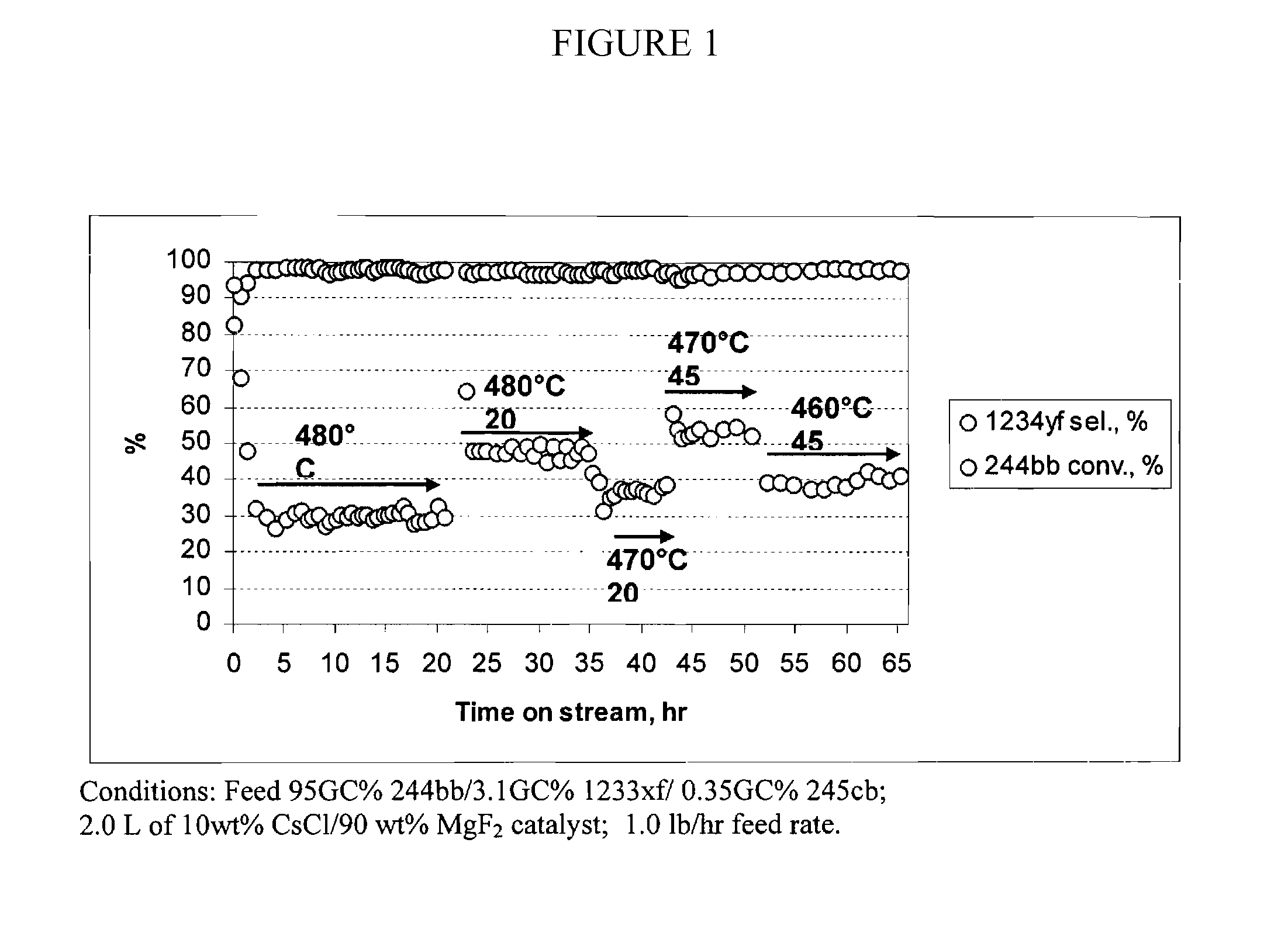
[0063]This example illustrates the continuous vapor phase dehydrochlorination reaction of 2-chloro-1,1,1,2-tetrafluoropropane (244bb)→2,3,3,3-tetrafluoropropene (1234yf)+HCl. The dehydrochlorination catalyst for the experiment was 10 wt % CsCl / 90 wt % MgF2.
[0064]Conversion of HCFC-244bb into HFO-1234yf was performed using a Monel reactor (ID 2 inch, length 32 inch) equipped with a Monel preheater (ID 1 inch, length 32 inch) which was filled with Nickel mesh to enhance heat transfer. The reactor was filled with 2.0 L of pelletized 10 wt % CsCl / 90 wt % MgF2 dehyrochlorination catalyst. Nickel mesh was placed at the top and at the bottom of reactor to support the catalyst. Multi-point thermocouple was inserted at the center of the reactor. The catalyst was pretreated in dry N2 flow for 6 hours at the temperature of 480° C. Then the feed with the composition 95 GC % 244bb / 3.1 GC % 1233xf / 0.35 GC % 245cb was introduced into the reactor at the rate of 1.0 lb / hr. The feed vaporized prior e...
PUM
| Property | Measurement | Unit |
|---|---|---|
| Temperature | aaaaa | aaaaa |
| Temperature | aaaaa | aaaaa |
| Temperature | aaaaa | aaaaa |
Abstract
Description
Claims
Application Information