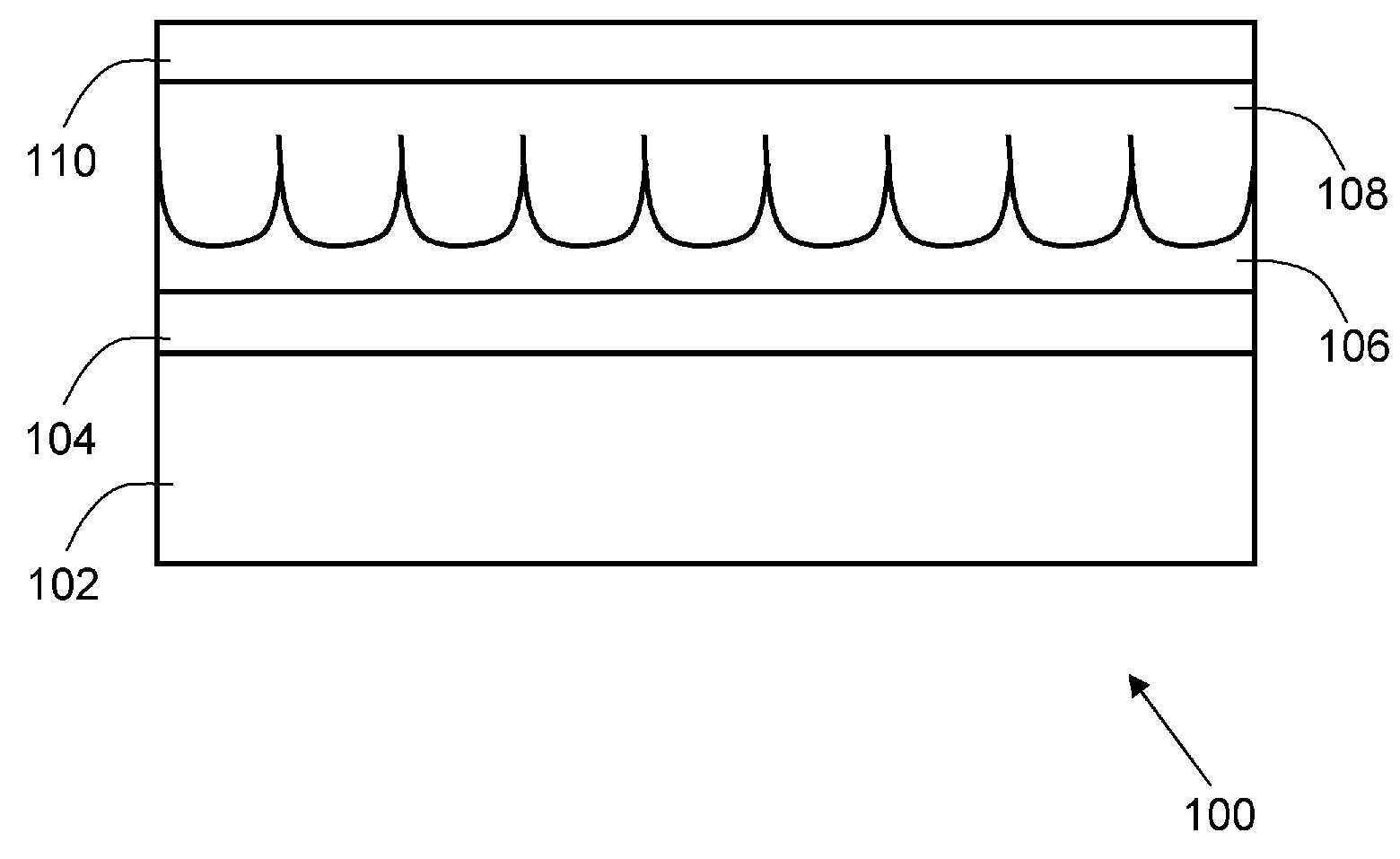
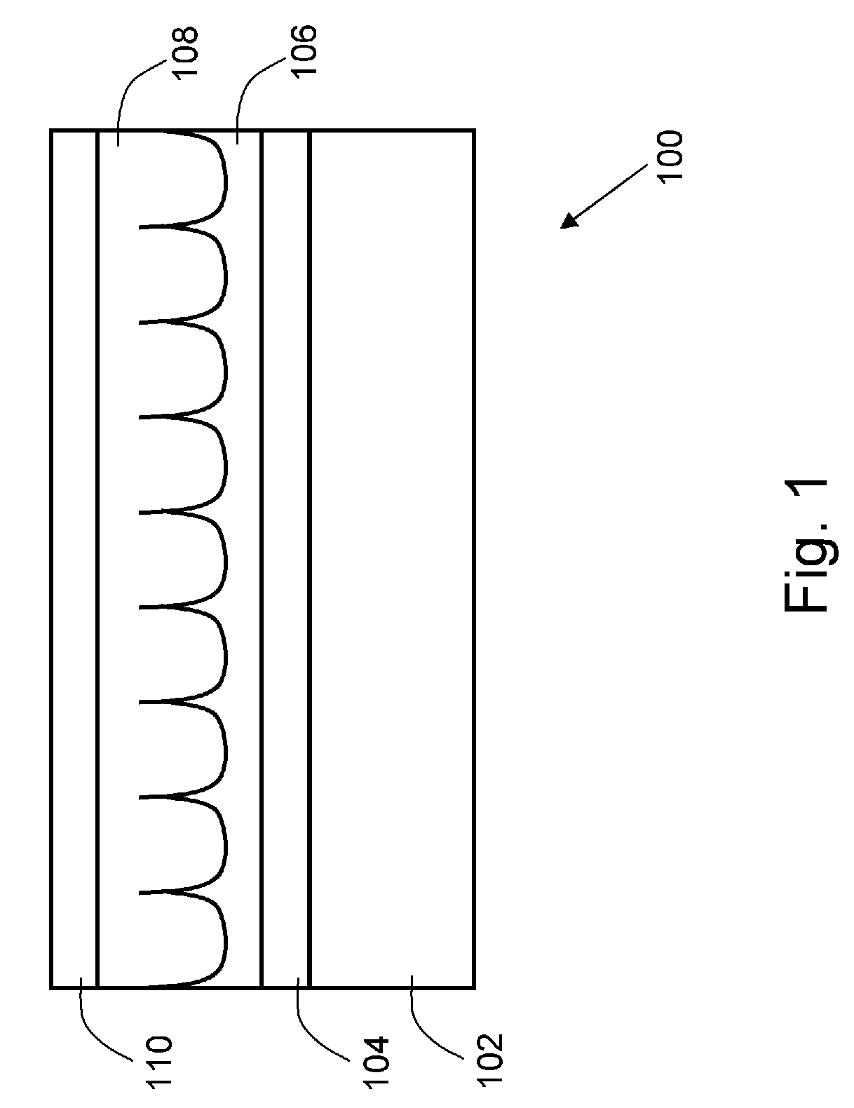
Hybrid photovoltaic modules
a photovoltaic module and hybrid technology, applied in the field of photovoltaic modules, can solve the problems of inability to reach the electrode, high cost, and low efficiency of photovoltaic modules, and achieve the effects of high efficiency, easy manufacturing, and high separation of charge carriers at the interfa
- Summary
- Abstract
- Description
- Claims
- Application Information
AI Technical Summary
Benefits of technology
Problems solved by technology
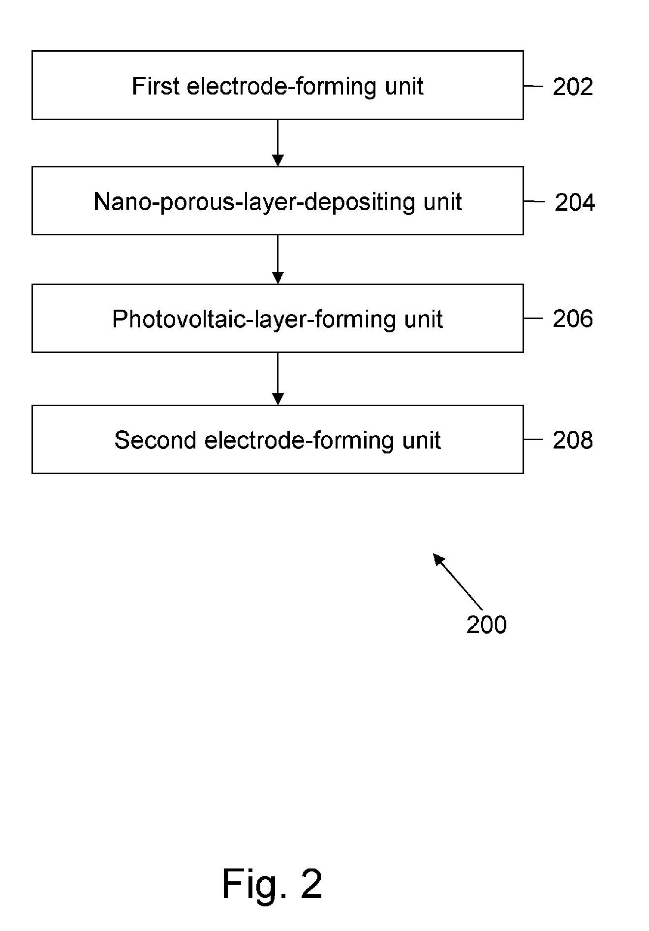
Method used
Image

Examples
Embodiment Construction
[0034]As used in the specification and claims, the singular forms “a”, “an” and “the” include plural references unless the context clearly dictates otherwise. For example, the term “a photovoltaic module” may include a plurality of photovoltaic modules unless the context clearly dictates otherwise.
[0035]Embodiments herein provide a photovoltaic module, a method and system for manufacturing the photovoltaic module, a system for generating electricity from solar energy, and a method of manufacturing the system for generating electricity from solar energy. In the description of the embodiments herein, numerous specific details are provided, such as examples of components and / or mechanisms, to provide a thorough understanding of embodiments herein. One skilled in the relevant art will recognize, however, that an embodiment herein can be practiced without one or more of the specific details, or with other apparatus, systems, assemblies, methods, components, materials, parts, and / or the l...
PUM
| Property | Measurement | Unit |
|---|---|---|
| Thickness | aaaaa | aaaaa |
| Thickness | aaaaa | aaaaa |
| Size | aaaaa | aaaaa |
Abstract
Description
Claims
Application Information
 - R&D
- Intellectual Property
- Life Sciences
- Materials
- Tech Scout
- Unparalleled Data Quality
- Higher Quality Content
- 60% Fewer Hallucinations
Browse by: Latest US Patents, China's latest patents, Technical Efficacy Thesaurus, Application Domain, Technology Topic, Popular Technical Reports.
© 2025 PatSnap. All rights reserved.Legal|Privacy policy|Modern Slavery Act Transparency Statement|Sitemap|About US| Contact US: help@patsnap.com