
Edge glow protection for composite component

a composite component and glow protection technology, applied in the field of composite components, can solve the problems of brittle and likely to shatter the edge seal of the prefabricated edge seal, high pressure gasses, and shattering the edge seal, and achieve the effects of reducing the void in the laminate structure, high structural integrity, and low possibility of edge glow

Inactive Publication Date: 2011-01-13
AIRBUS OPERATIONS LTD
View PDF5 Cites 25 Cited by
  • Summary
  • Abstract
  • Description
  • Claims
  • Application Information

AI Technical Summary

Benefits of technology

[0012]The invention is advantageous in that the exposed lateral edge of the composite component is free of cut ply edges, which significantly reduces or eliminates the possibility of edge glow at the lateral edge. This is achieved without the need for capping of the lateral edge. This reduces part count, manufacturing time, ease of assembly to other components, and serviceability. By turning one or more of the plies at the lateral edge, the component may also exhibit improved strength. The turned plies can transfer load more efficiently into the second component of the assembly and reduce stress concentrations, and the lateral edge is less susceptible to delamination due to the elimination of exposed cut ply edges.
[0014]In a preferred embodiment, the lateral edge has a concave profile. This may be achieved by turning all but one of the plies, which reduces voids in the laminate structure so giving a high structural integrity and low possibility of edge glow.

Problems solved by technology

Firstly the prepreg material which forms the edge seal is brittle and likely to shatter in the event of a lightning strike.
Specifically, a lightning strike can result in the generation of high pressure gasses and / or plasma at the cut edge which may shatter the edge seal.
Secondly the bond between the prepreg material and the cut edge is relatively brittle, so the gasses and / or plasma may cause the bond to shatter.
Finally the U-shaped cross-sectional profile of the edge seal means that it is difficult to join the laminate to another component.
Also, it is difficult to remove and replace the edge seal for inspection or repair purposes.
This is because it is necessary to dismantle the joint in order to remove the seal, and because the nature of the adhesive bond between the cut edge and the prepreg makes it physically difficult to break.

Method used


Image

  • Edge glow protection for composite component
  • Edge glow protection for composite component
  • Edge glow protection for composite component

Examples


Embodiment Construction

)

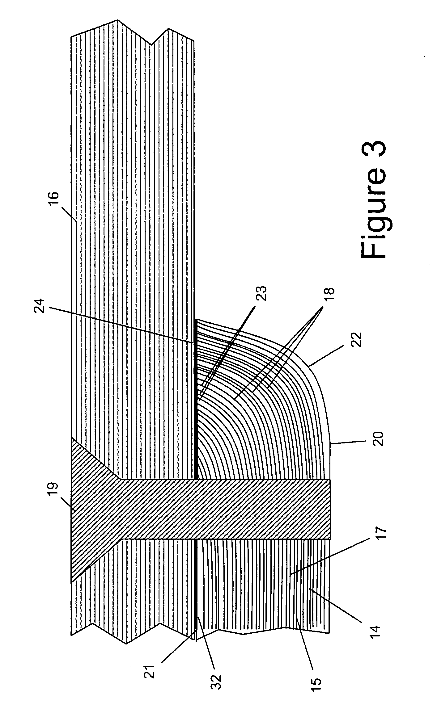
[0031]FIG. 3 shows in detail a joint between a cap 14 of a C-section spar 15 and an upper wing cover 16, which define, in part, walls of a fuel tank of an aircraft wing box.

[0032]The spar cap 14 is formed from a stack of plies 17 of carbon fibre-reinforced epoxy resin. The upper wing cover 16 is also formed from a stack of plies of carbon fibre-reinforced epoxy resin. Metal fasteners 19 are used to join the spar cap 14 to the upper cover 16.

[0033]The spar cap 14 has opposing first and second surfaces 20, 21 substantially parallel with the plane of the stack of plies 17 of the spar cap 14. A lateral edge 22 extends between the first and second surfaces 20, 21. The plies 17 each terminate at a cut ply edge 23. Unlike the joint shown in FIG. 2, the cut ply edges 23 of the plies 17 are not exposed at the lateral edge 22. Instead, the cut ply edges 23 are substantially flush with the second surface 21 and face outwardly therefrom.

[0034]This is achieved through turning the plies in the r...


PUM

PropertyMeasurementUnit
Fractionaaaaaaaaaa
Electrical conductoraaaaaaaaaa

Abstract

A composite component comprises a co-cured stack of composite laminate plies, and has a lateral edge between opposing first and second surfaces. The lateral edge is free of laterally facing cut ply edges, and at least one of the plies has a cut ply edge substantially flush with and facing outwardly from the second surface. The component may be joined to a second component such that the one or more outwardly facing cut ply edges face towards the second component. Eliminating exposed cut ply edges protects against edge glow. Also, methods of forming the composite component.

Description

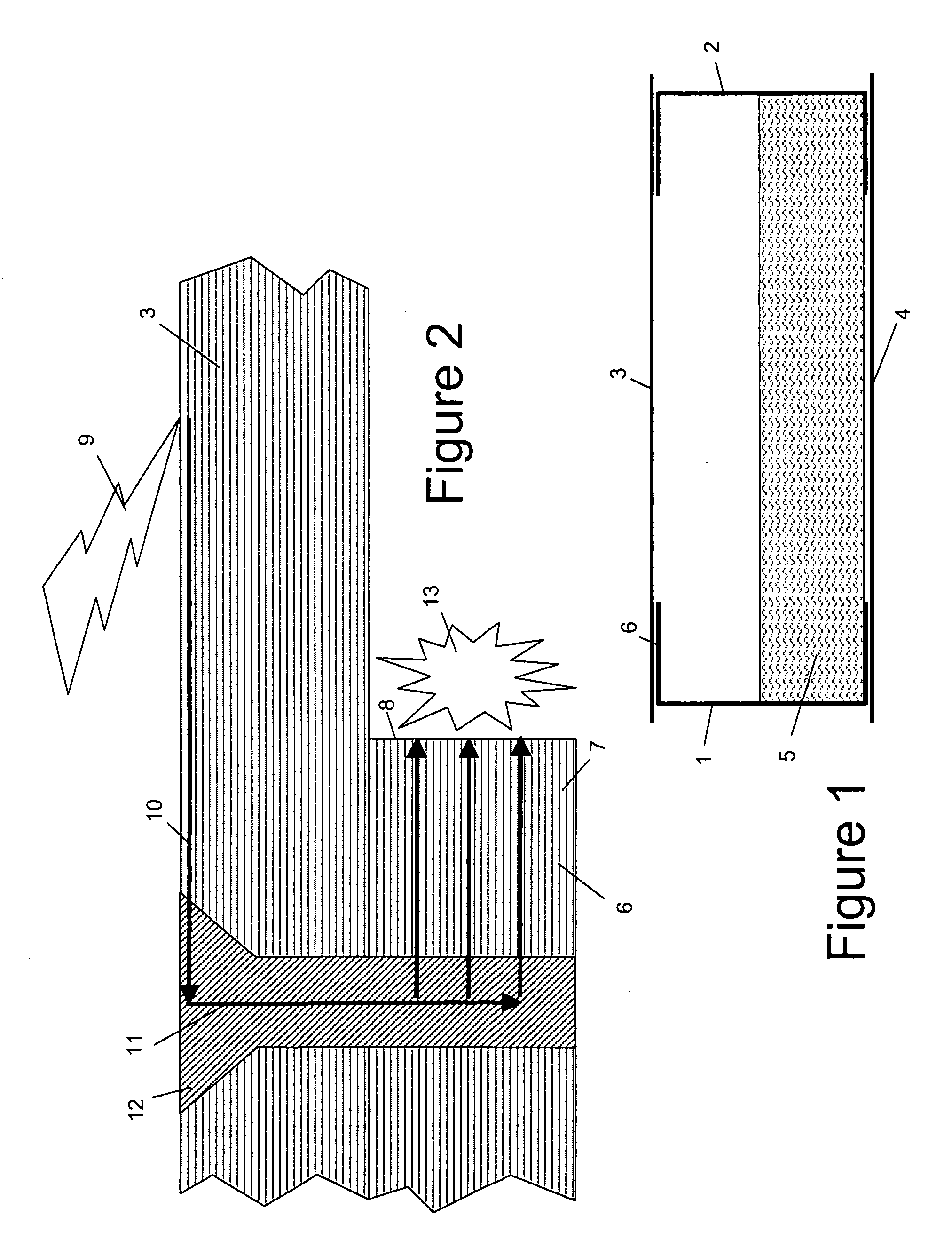
FIELD OF THE INVENTION[0001]The present invention relates to a composite component comprising a co-cured stack of composite laminate plies, which is less susceptible to edge glow.BACKGROUND OF THE INVENTION[0002]FIG. 1 is a schematic cross-sectional view through an aircraft wing box. The wing box has a pair of C-section spars 1, 2 and upper and lower covers 3, 4 which define the walls of a fuel tank containing fuel 5. FIG. 2 shows in detail the joint between a cap 6 of the spar 1 and the upper cover 3.[0003]The spar cap 6 is formed from a series of plies of carbon fibre-reinforced epoxy resin. Some of the layers of carbon fibre 7 are shown in FIG. 2, and these fibres terminate at a cut edge 8. If a lightning strike 9 hits the upper cover 3, then current 10 tends to run along a bronze mesh (not shown) on the external surface of the cover 3, down the metal fasteners 12 which join the spar cap to the cover, and along the carbon fibre layers in the spar cap 6 up to the cut edge 8 which ...

Claims


Application Information

Patent Timeline
IPC IPC(8): B32B3/04B32B37/00
CPCB29C35/02Y10T156/1034B29C66/474B29C66/721B29C66/73752B29C67/0044B29C70/34B29C70/882B29K2063/00B29K2105/246B29K2307/00B29K2707/04B29L2031/3085B32B3/04B32B2038/0076B32B2305/076B64D45/02B64F5/0009B29C66/524Y10T428/24777B29C66/43441B29C66/7212B29C66/71B29C66/72141B29C66/73941B29C65/02B32B5/022B32B5/024B32B5/26B32B7/12B32B2250/20B32B2250/44B32B2260/023B32B2260/046B32B2262/106B32B2307/202B32B2307/50B32B2439/62B32B2605/18B64F5/10B29C66/112B29C66/1122B29C66/131B29C70/302B29K2307/04
Inventor RUSKIN, EDWARD
Owner AIRBUS OPERATIONS LTD
Learn More