Device and methods for delivery and transfer of temporary radiopaque element

a radiopaque element and device technology, applied in the field of devices and methods for delivery and transfer of temporary radiopaque elements, can solve the problems of high incidence of procedure-related death, high risk of valve prosthesis placement, and significant challenge in the placement of valve prosthesis during transcatheter procedures, so as to achieve the effect of reducing the complication of the procedure, facilitating the placement of the prosthesis aortic valve, and avoiding complications

a radiopaque element and device technology, applied in the field of devices and methods for delivery and transfer of temporary radiopaque elements, can solve the problems of high incidence of procedure-related death, high risk of valve prosthesis placement, and significant challenge in the placement of valve prosthesis during transcatheter procedures, so as to achieve the effect of reducing the complication of the procedure, facilitating the placement of the prosthesis aortic valve, and avoiding complications

US20110009818A1Active Publication Date: 2011-01-13GOFF THOMAS G

Image

  • Device and methods for delivery and transfer of temporary radiopaque element
  • Device and methods for delivery and transfer of temporary radiopaque element
  • Device and methods for delivery and transfer of temporary radiopaque element

Examples


Embodiment Construction

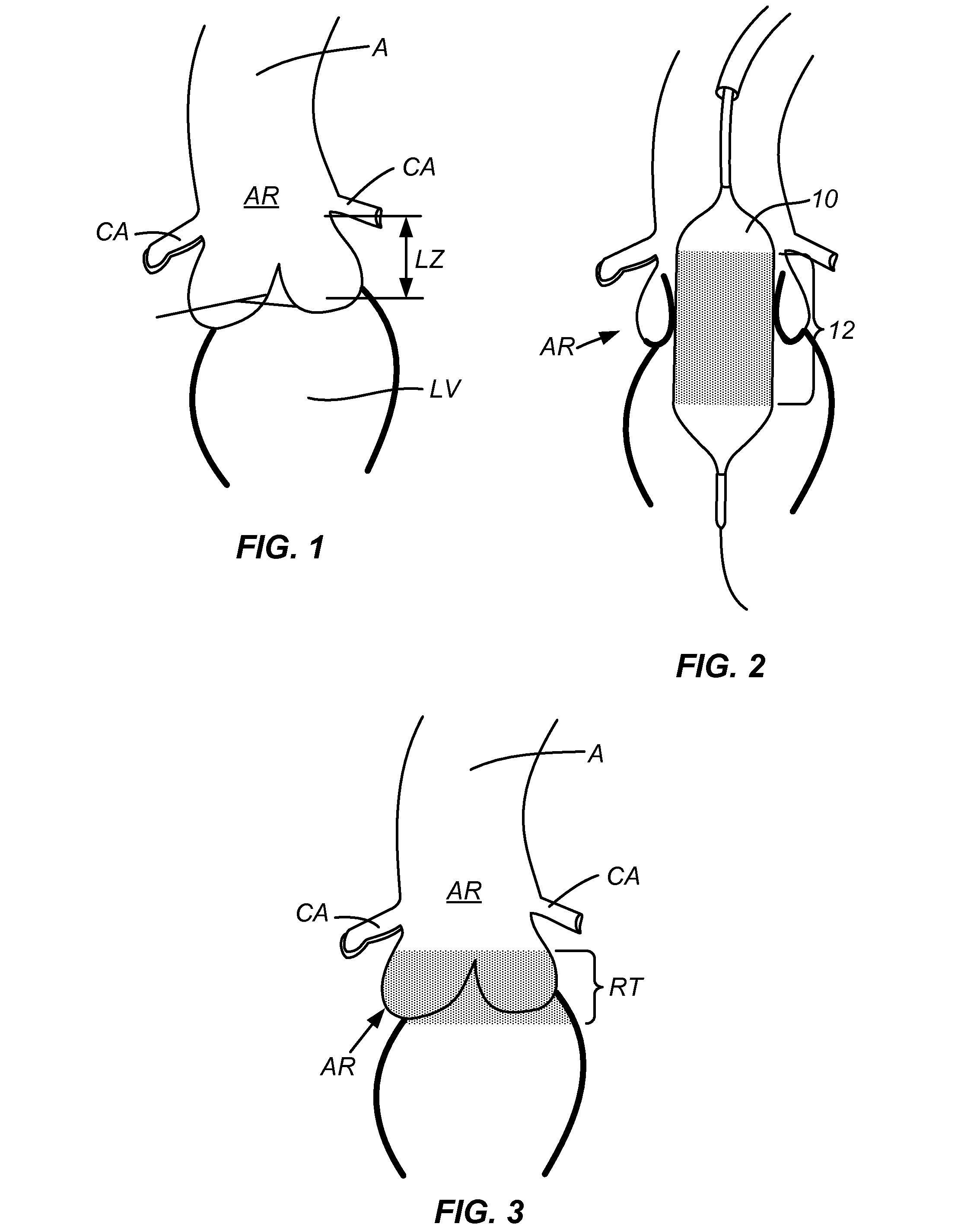
[0021]FIG. 1 shows the geometry of the aortic root AR. Of note is the narrow landing zone LZ for a prosthetic valve. This zone is bounded by the aorta A and coronary arteries CA above and the left ventricle LV below. This narrow working space makes the percutaneous placement of a prosthetic aortic valve very challenging.

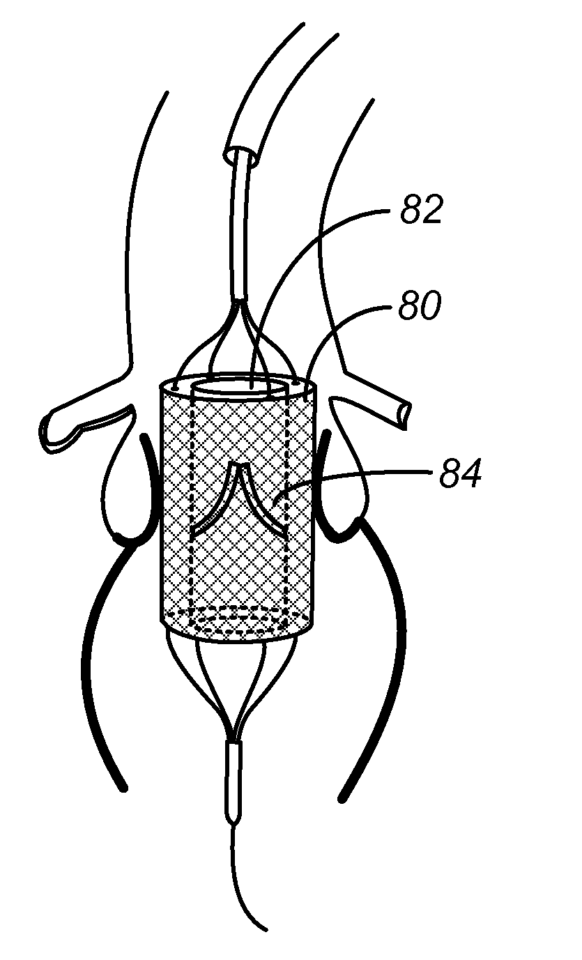
[0022]FIG. 2 shows a balloon 10 coated with a radiopaque dye 12 or other radiopaque material during a balloon aortic valvuloplasty in the aortic root AR. During this inflation, the radiopaque material will be transferred to the surrounding tissues, where FIG. 3 shows the region of transfer RT of the radiopaque material. Since the prosthetic valve is desired to be placed at the annulus, or region of greatest narrowing, the radiopaque element will naturally have transferred to the desired transfer region as the expanding balloon will engage the narrowest region first.

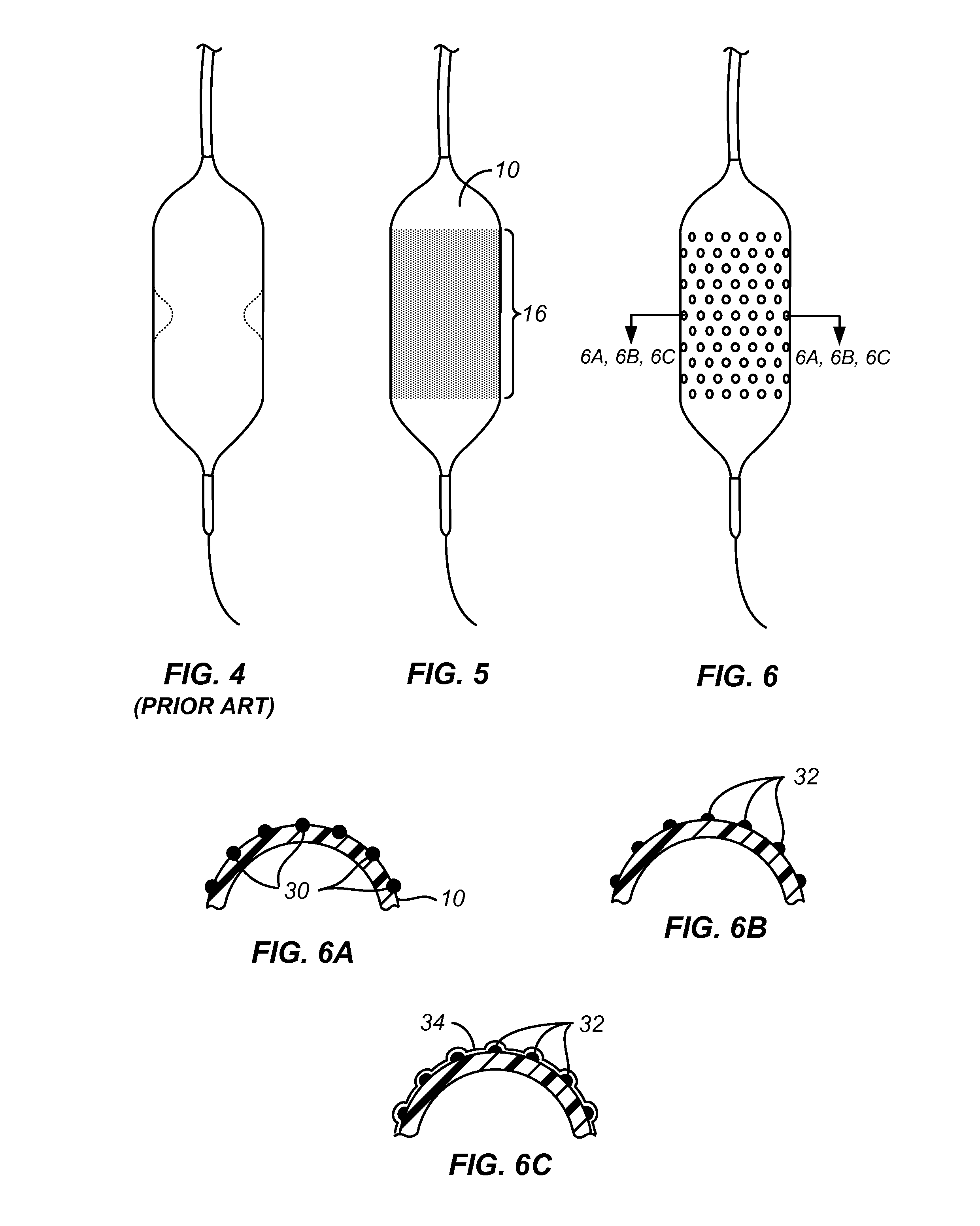
[0023]FIG. 4 shows a standard valvuloplasty balloon. Such valvuloplasty balloons are available from a n...


PUM


Abstract

A device for the transfer of radiopaque material within the body comprises a valvuloplasty or other balloon coated with the radiopaque material. The balloon is inflated in the aortic valve for marking the site of an aortic annulus to enable accurate placement of prosthetic valves under fluoroscopic imaging.

Description

CROSS-REFERENCES TO RELATED APPLICATIONS[0001]The present application claims the benefit of U.S. Provisional Patent Application No. 61 / 223,640 (Attorney Docket No. 028053-000100US), filed Jul. 7, 2009, the entire contents of which are incorporated herein by reference.BACKGROUND OF THE INVENTION[0002]Many complex medical interventions rely on the imaging of internal body structures through less invasive means to identify structures and perform procedures without direct visualization. Such indirect visualization means include radiographic imaging such as x-ray fluoroscopy, echocardiography, ultrasound, nuclear magnetic resonance imaging, and tomography. As medical techniques continually evolve to be less invasive, these imaging techniques become more necessary.[0003]X-ray fluoroscopy is used during many percutaneous and natural orifice surgical procedures and intravascular cardiovascular procedures. Percutaneous transcatheter procedures have become the standard of care for many cardio...

Claims


Application Information

Patent Timeline
13 Jan 2011
Publication
US20110009818A1
IPC
A61M29/00; A61M25/10
CPC
A61B19/54; A61B2019/5466; A61F2/24; A61M25/0108; A61M25/10; A61M29/02; A61B2019/5483; A61M2025/1075
Inventors
GOFF, THOMAS G.