Power factor correction and driver circuits

a driver circuit and power factor technology, applied in the direction of efficient power electronics conversion, electric lighting sources, electric light sources, etc., can solve the problems of increased power loss through transmission and distribution lines, increased operating costs, and additional costs for power companies, so as to increase and uniformize power and current regulation, the effect of high voltag

Inactive Publication Date: 2011-01-20
LSI INDS
View PDF64 Cites 19 Cited by
  • Summary
  • Abstract
  • Description
  • Claims
  • Application Information

AI Technical Summary

Benefits of technology

[0026]A further aspect of the present disclosure relates to and can provide high-voltage driver circuits configured for electrical loads such as series arrangements of LEDs. An exemplary embodiment of such a drive stage or circuit can implement a comparator and / or a voltage regulator to allow for improved output current uniformity for high-voltage applications and loads, such as series configurations of LEDs.

Problems solved by technology

Electrical loads consuming alternating current power consume both real power, which does or is able to do useful work, and reactive power, which dissipates no energy in the load and which returns to the source on each alternating current cycle.
The reactive power increases the current flowing between the power source and the load, which increases the power losses through transmission and distribution lines.
This results in additional costs for power companies.
In addition to the increased operating costs, reactive power can require the use of wiring, switches, circuit breakers, transformers and transmission lines with higher current capacities.
The problem with this is that the rectifier is a non-linear device, so the input current is highly non-linear.
This presents a particular problem for the power companies, because they cannot compensate for the harmonic current by adding simple capacitors or inductors, as they could for the reactive power drawn by a linear load.
The large spikes in the current waveform are caused because of the switching power supply and its use of the rectifier bridge / smoothing capacitor circuits.
This filter requires large-value high-current inductors, however, which are bulky and expensive.
It is not as effective as active PFC.
The electricity generator, with no power factor correction, must supply energy at the top / peak of the sine wave rather than throughout the cycle, which can cause the sine wave to collapse around its peak.
For some applications, including those providing power at relatively high voltages, such previously described PFC techniques can present or allow for undesirable losses in efficiency due to non unity PFC values.
Such regulators and PFC techniques, however, have been shown to have less than optimal current control.
This in turn can lead to unacceptable variation in current delivery, with attendant component longevity reductions and thermal management issues.
What is currently lacking, therefore, are techniques for providing power factor correction values closer to unity under a variety of operating condition and for relatively high voltages.

Method used


Image

  • Power factor correction and driver circuits
  • Power factor correction and driver circuits
  • Power factor correction and driver circuits

Examples


Embodiment Construction

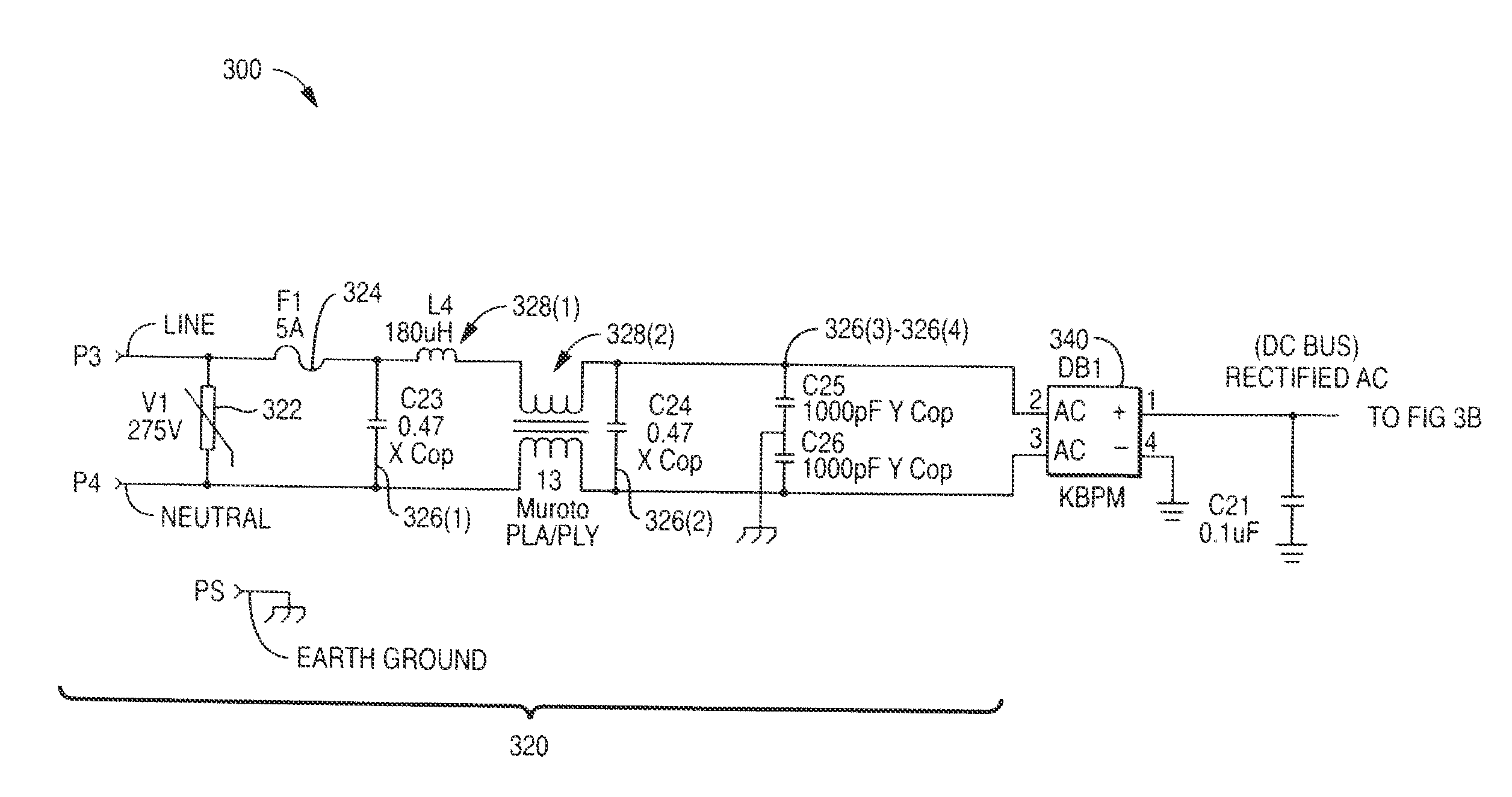
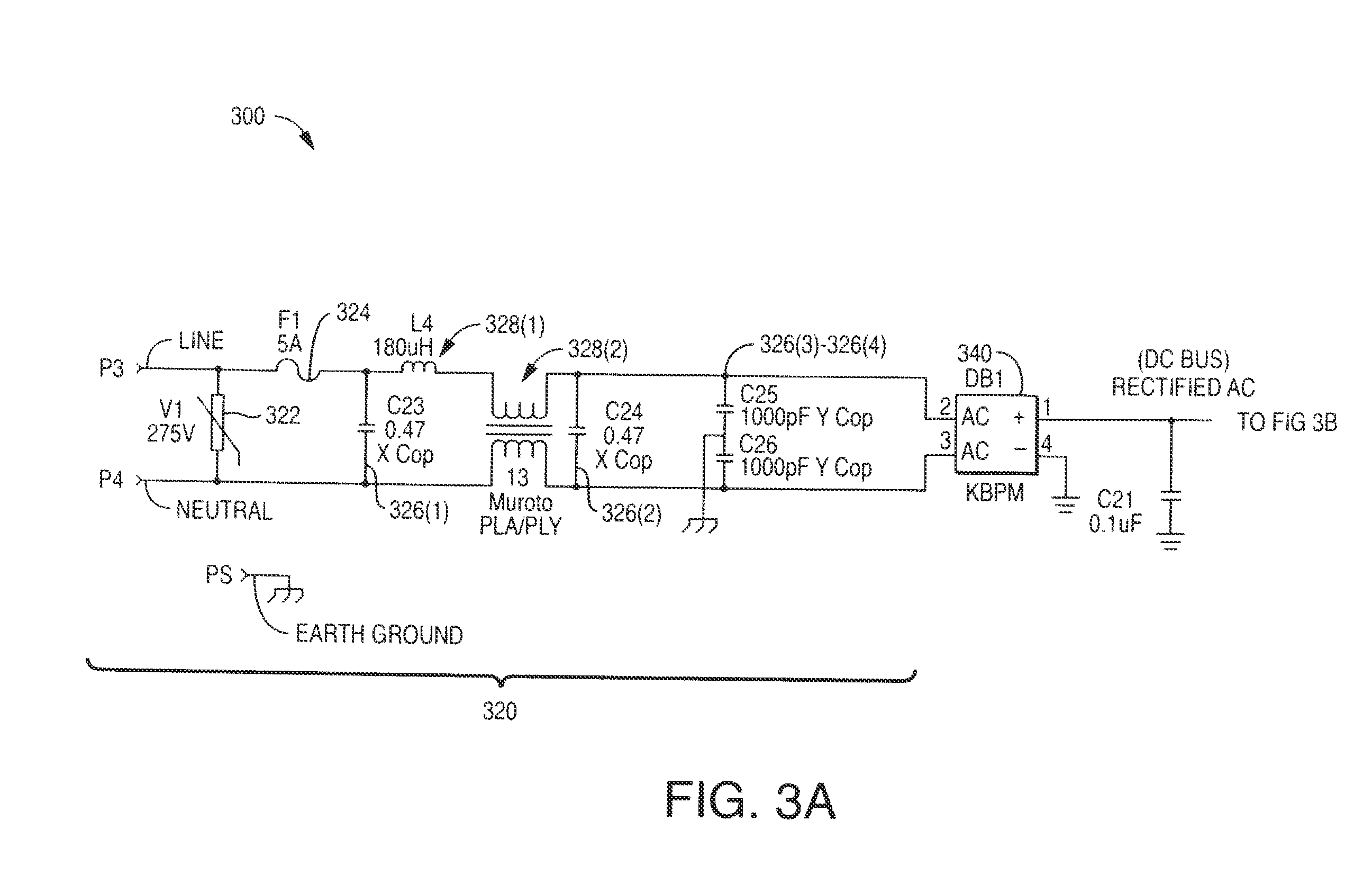
[0038]Aspects and embodiments of the present disclosure provide circuits / stages that can be utilized for power factor correction and / or electric device / component driver functionality. Such stages or circuits can be used to increase power factor correction and / or power regulation and improve service life of electrical loads. e.g., series configurations of LEDs and related components, as well as reduce thermal losses and costs related to such.

[0039]A further aspect of the present disclosure relates high-voltage driver circuits configured for electrical loads such as series arrangements of light emitting diodes. An exemplary embodiment of a drive circuit can implement a comparator and / or a voltage regulator to allow for improved output current uniformity for high-voltage applications and loads, such as series configurations of LEDs.

[0040]Aspects and embodiments of the present disclosure may be more fully understood from the description herein when read together with the accompanying dr...


PUM


Abstract

Power factor correction and driver circuits and stages are described. More particularly, power factor correction circuits are described that utilize an auxiliary inductor winding for power regulation. Driver circuits configured for electrical loads such as series arrangements of light emitting diodes are also described. An exemplary embodiment of a driver circuit can implement a comparator and / or a voltage regulator to allow for improved output current uniformity for high-voltage applications and loads, such as series configurations of LEDs. Embodiments of PFC stages and driver stages can be combined for use as a power supply, and may be configured on a common circuit board. Power factor correction and driver circuits can be combined with one or more lighting elements as a lighting apparatus.

Description

RELATED APPLICATIONS[0001]This application is a continuation and claims the benefit U.S. application Ser. No. 12 / 112,101, filed on Apr. 30, 2008. The entire contents of each of the foregoing applications are incorporated herein by reference.FIELD OF THE DISCLOSURE[0002]The present disclosure relates generally to power factor correction and driver circuits. More particularly, the present disclosure relates to power factor correction circuits utilizing an auxiliary inductor winding for power regulation and also high-voltage driver circuits configured for electrical loads such as series arrangements of light emitting diodes (“LEDs”).BACKGROUND OF THE DISCLOSURE[0003]Power factor is the ratio of real power to apparent power. In the United States, power is provided at approximately 120 Volts AC with a frequency of approximately 60 Hertz. In Europe and other areas, power is provided at approximately 240 Volts AC with a frequency of approximately 50 Hertz.[0004]Power factor correction (PFC...

Claims


Application Information

Patent Timeline
Patent Type & Authority Applications(United States)
IPC IPC(8): H05B41/16H05B44/00
CPCH02M1/4225H05B33/089Y02B70/126H05B33/0815Y02B70/10H05B45/38H05B45/355
Inventor KELLY, KEVIN ALLAN
Owner LSI INDS
Why Eureka
Try Eureka