
Current-input current-output reconfigurable passive reconstruction filter

a passive reconstruction and current input technology, applied in filters, frequency selective two-port networks, code conversion, etc., can solve the problems of large area, power consumption, cost savings, etc., and achieve the effect of high linearity, highly programmable, and easily reconfigurable reconstruction filters

Inactive Publication Date: 2011-01-20
AVAGO TECH WIRELESS IP SINGAPORE PTE
View PDF4 Cites 8 Cited by
  • Summary
  • Abstract
  • Description
  • Claims
  • Application Information

AI Technical Summary

Benefits of technology

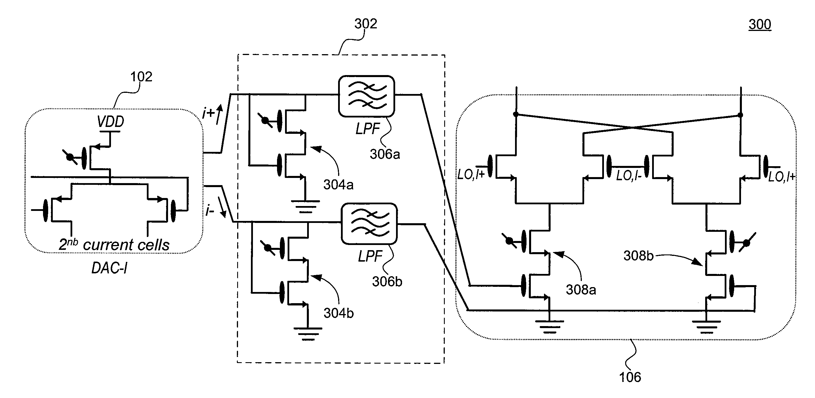
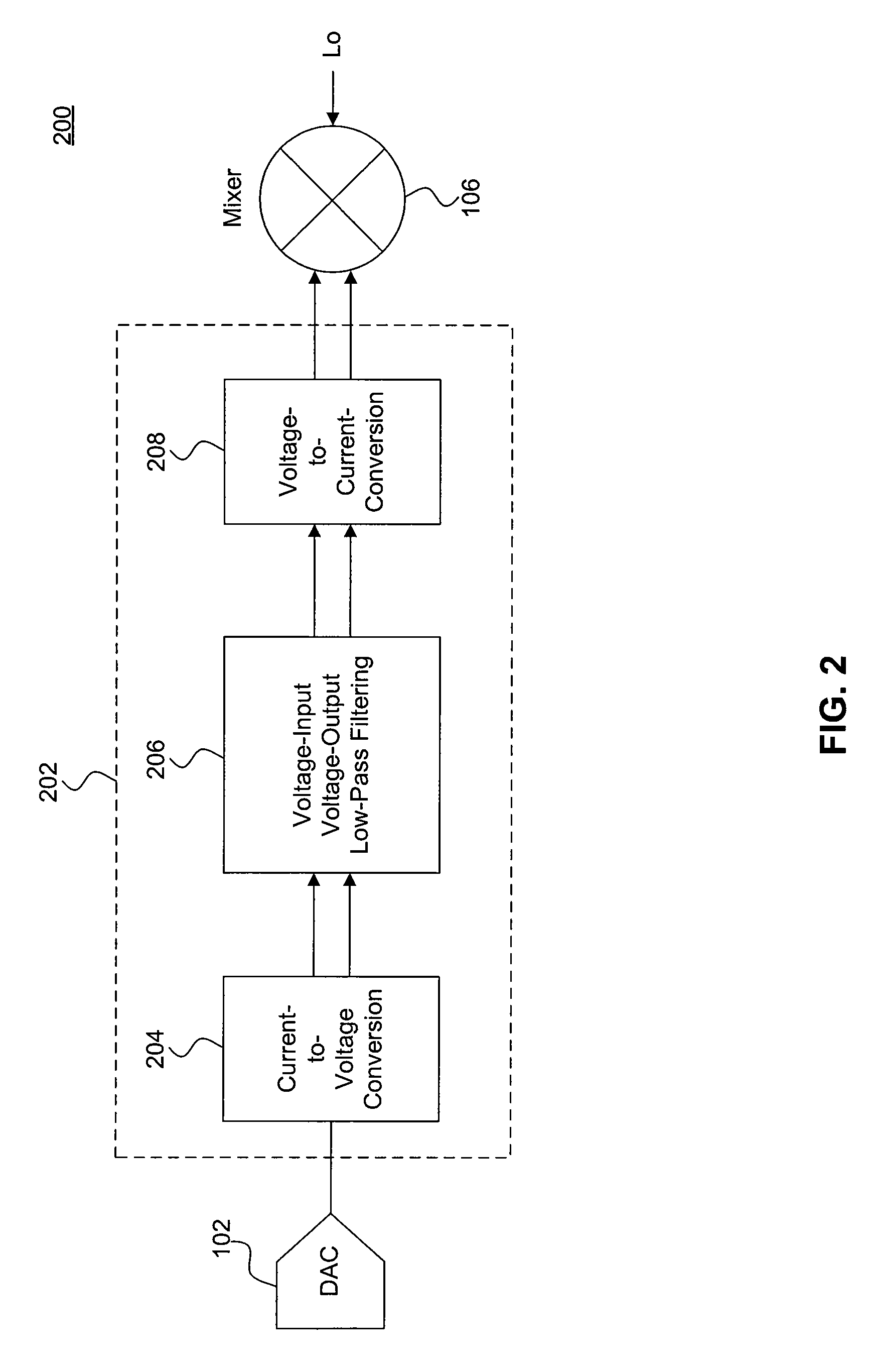
[0007]Embodiments of the present invention relate generally to reconstruction filtering. In particular, embodiments enable highly linear, highly programmable, and easily reconfigurable reconstruction filters. Further, embodiments provide substantial power consumption, area, and cost savings compared to conventional solutions. For example, embodiments use all-passivefiltering and substantially reduce active elements compared to conventional solutions. As a result, significant reductions in required area, noise, and power consumption can be achieved. In addition, embodiments perform filtering solely in the current domain, thereby eliminating the non-linear voltage-to-current conversion used in conventional circuits and enabling highly linear filtering. Furthermore, embodiments are highly programmable and easily reconfigurable without the use of tunable capacitors. As such, embodiments are very suitable solutions for multi-band multi-mode wireless transmitters.

Problems solved by technology

Further, embodiments provide substantial power consumption, area, and cost savings compared to conventional solutions.

Method used


Image

  • Current-input current-output reconfigurable passive reconstruction filter
  • Current-input current-output reconfigurable passive reconstruction filter
  • Current-input current-output reconfigurable passive reconstruction filter

Examples


example implementation 500

[0050]Example implementation 500 is structurally similar to example implementation 400, but also includes an output transistor 502, as shown in FIG. 5. Output transistor 502 has a drain terminal coupled to input node 402, a source terminal coupled to ground, and a gate terminal coupled to the gate terminal of input transistor 420 of the mixer.

[0051]The transfer function of the reconstruction filter of FIG. 5 can be written as:

H(s)=Vois=1R1R2C1C2C3s3+(R2C2C3+R1C1C2+R1C1C3+R2C1C2)s2+(C1+C2+C3+gm1R2C2)s+gm1+gm2

where VO represents the voltage at the input of the mixer, as shown in FIG. 5.

[0052]In an embodiment, input transistor 406 and output transistor 502 are matched according to a transconductance ratio, which allows example implementation 500 to have a smaller area compared to example implementation 400. Further, example implementation 500 may be suited for cases in which input current signal iS 404 has a small AC signal swing (e.g., less than 25%).

[0053]FIG. 6 illustrates another e...

example implementation 600

[0054]Example implementation 600 is structurally similar to example implementation 400, but also includes a diode-connected transistor 602 having a first terminal and a second terminal coupled to input node 402 and a third terminal coupled to ground. The transfer function of the reconstruction filter of FIG. 6 can be written as:

H(s)=Vois=1R1R2C1C2C3s3+(R2C2C3+R1C1C2+R1C1C3+R2C1C2+gm2R1R2C2C3)s2+(C1+C2+C3+gm1R2C2+gm2(R1C3+R2C2+R1C2))s+gm1+gm2

where VO represents the voltage at the input of the mixer, as shown in FIG. 6.

[0055]FIG. 7 illustrates another example implementation 700 of a reconstruction filter according to an embodiment of the present invention. Similar to FIG. 4, FIG. 7 shows a reconstruction filter according to an embodiment of the present invention coupled to the input stage of a subsequent circuit. In an embodiment, the subsequent circuit includes a mixer, as shown above in FIG. 3.

example implementation 700

[0056]Example implementation 700 is structurally similar to example implementation 400, but also includes an operational amplifier 702 coupled between input transistor 406 and RC network 408. As such, the first and third terminals of input transistor 406 are coupled to one another and also to the inverting input of operational amplifier 702. The non-inverting input of operation amplifier 702 is coupled to the second end of first resistor R1 412, forming a feedback loop in the reconstruction filter. The output terminal of operational amplifier 702 is coupled to the first end of first resistor R1 412.

[0057]The transfer function of the reconstruction filter of FIG. 7 can be written as:

H(s)=iois=gmR1R2C1C2C3s3+(R2C2C3+R1C3C2+R1C1C3+R2C1C2)s2+(C1+C2+C3+gm1R2C2)s+gm.

[0058]As would be understood by a person skilled in the art based on the teachings herein, example implementations 500, 600, and 700 have similar functionality, operation, and performance as described above with respect to exa...


PUM


Abstract

Embodiments of the present invention relate generally to reconstruction filtering. In particular, embodiments enable highly linear, highly programmable, and easily reconfigurable reconstruction filters. Further, embodiments provide substantial power consumption, area, and cost savings compared to conventional solutions. For example, embodiments use all-passive filtering and substantially reduce active elements compared to conventional solutions. As a result, significant reductions in required area, noise, and power consumption can be achieved. In addition, embodiments perform filtering solely in the current domain, thereby eliminating the non-linear voltage-to-current conversion used in conventional circuits and enabling highly linear filtering. Furthermore, embodiments are highly programmable and easily reconfigurable without the use of tunable capacitors. As such, embodiments are very suitable solutions for multi-band multi-mode wireless transmitters.

Description

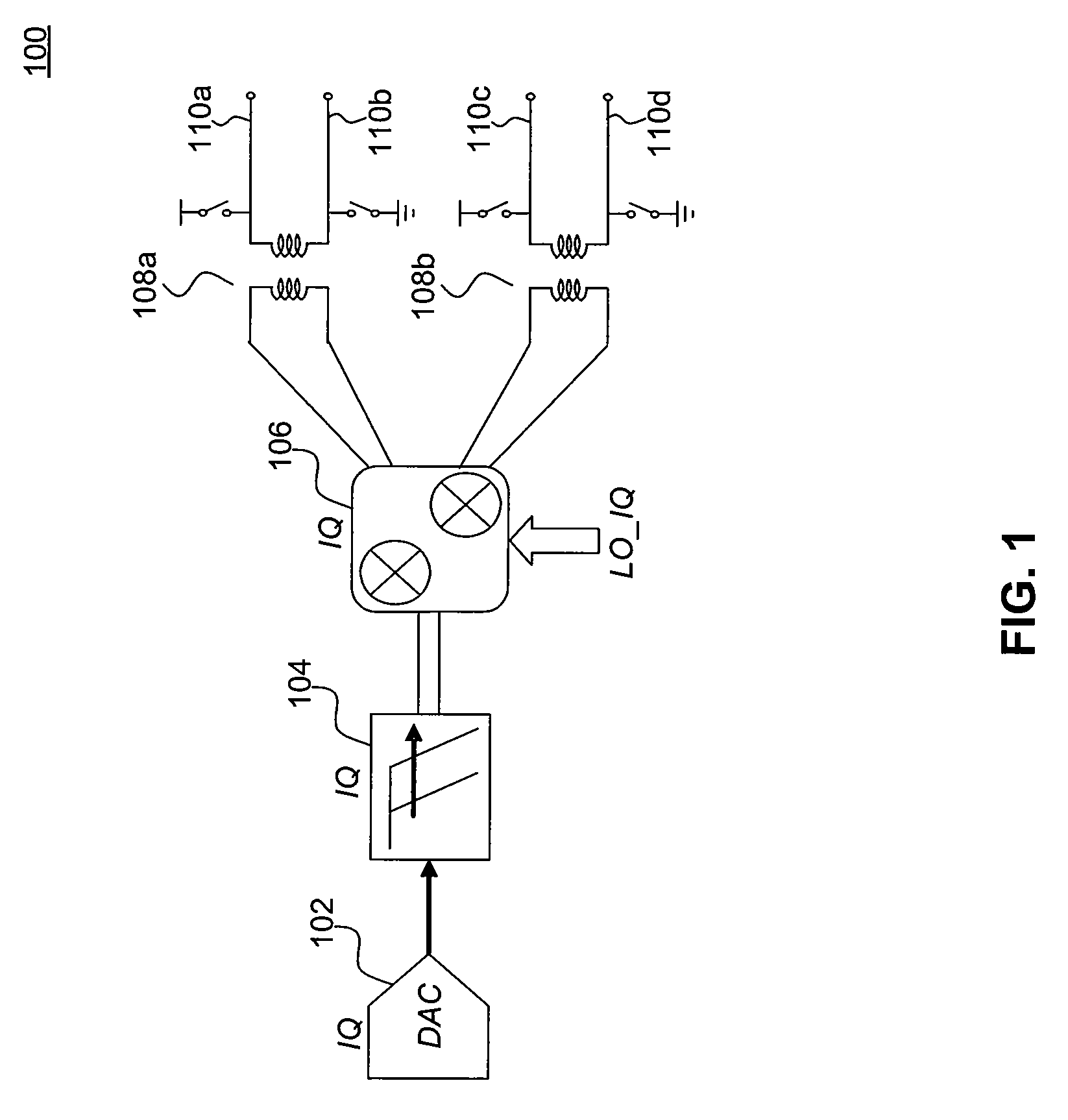
BACKGROUND[0001]1. Field of the Invention[0002]The present invention relates generally to reconstruction filtering.[0003]2. Background Art[0004]In practice, the output of a digital-to-analog converter (DAC) needs to be band-limited to prevent aliasing. For this reason, a low-pass filter, called reconstruction filter, is typically used at the output of the DAC in order to reduce unwanted images of the information signal.[0005]Conventional reconstruction filtering solutions have a number of drawbacks, including being inherently non-linear, using many active elements, and being difficult to reconfigure. These drawbacks make conventional solutions unsuitable for use in multi-band multi-mode wireless transmitters, for example, which require reconstruction filters with high bandwidth programmability and reconfigurability. In addition, conventional solutions are high in cost, power consumption, and area requirements.[0006]Accordingly, there is a need for improved reconstruction filtering s...

Claims


Application Information

Patent Timeline
IPC IPC(8): H03H7/12
CPCH03H1/02H03H7/12H03H11/0427H03H11/04H03M1/661H03H2250/00H03H11/1213
Inventor MIRZAEI, AHMADDARABI, HOOMAN
Owner AVAGO TECH WIRELESS IP SINGAPORE PTE
Learn More