Method for producing ceramic nanoparticles

a technology of ceramic nanoparticles and nanoparticles, which is applied in the direction of chemical/physical processes, alkaline earth titanates, inorganic chemistry, etc., can solve the problem that the common method of forming ceramics cannot be applied to ceramic nanoparticles, and achieve the effect of increasing the size and high the productive efficiency

Active Publication Date: 2011-01-20
M TECHN
View PDF3 Cites 27 Cited by
  • Summary
  • Abstract
  • Description
  • Claims
  • Application Information

AI Technical Summary

Benefits of technology

[0013]The present invention relates to a method for producing ceramic nanoparticles in which ceramic nanoparticles are obtained by hydrolyzing a ceramic material in a thin film fluid formed between processing surfaces arranged to be opposite to each other to be able to approach to and separate from each other, at least one of which rotates relative to the other, wherein monodisperse ceramic nanoparticles having a smaller average particle size than that of ceramic nanoparticles obtained by conventional reaction methods can be obtained. Further, the present invention provides a method for producing ceramic nanoparticles, wherein ceramic nanoparticles can be obtained continuously and efficiently with high productive efficiency for manufacturing. Moreover, the present invention provides a method for producing ceramic nanoparticles with an apparatus capable of increasing in size with a common scale-up concept depending on necessary production.

Problems solved by technology

Generally, ceramic particles are obtained by hydrolyzing alkoxide- or metal salt-based ceramic materials, but a common method of forming ceramics cannot be applied to ceramic nanoparticles because of their strong cohesion.

Method used


Image

  • Method for producing ceramic nanoparticles
  • Method for producing ceramic nanoparticles
  • Method for producing ceramic nanoparticles

Examples


example 1

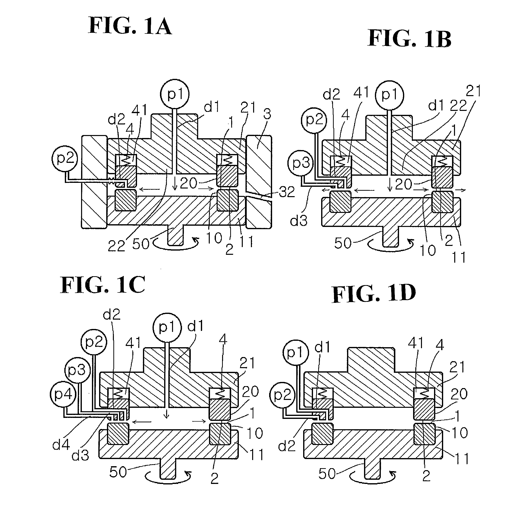
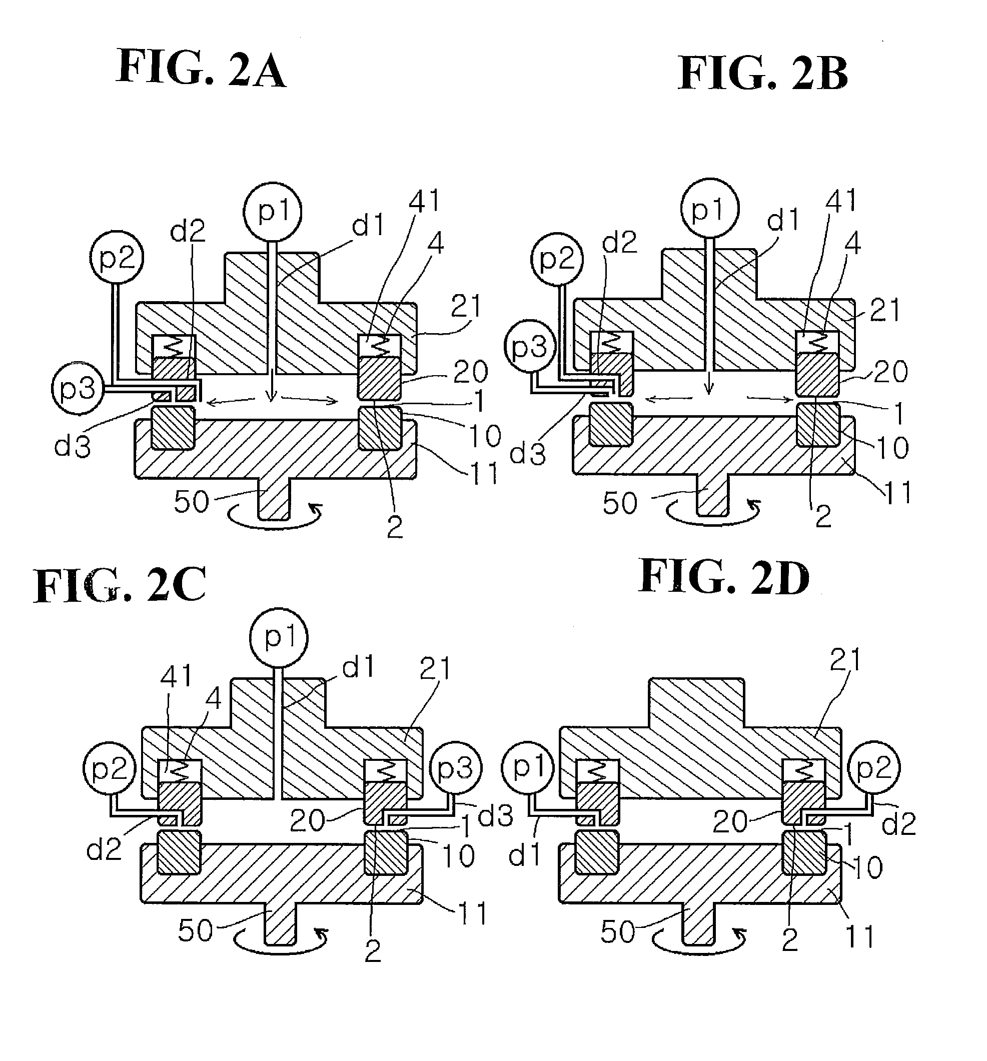
[0381]An aqueous solution adjusted to pH 2 with an aqueous solution of hydrochloric acid flows into an aqueous solution of IPA containing ceramics materials in a thin film fluid formed between the processing surfaces 1 and 2 arranged to be opposite to each other so as to be able to approach to and separate from each other, at least one of which rotates relative to the other, in use of a uniformly stirring and mixing reaction apparatus as shown in FIG. 1(A), thereby effecting hydrolysis reaction under uniform mixing in the thin film.

[0382]While an aqueous solution adjusted to pH 2 with an aqueous solution of hydrochloric acid was sent as a first fluid from the center at a supply pressure / back pressure of 0.30 MPa / 0.01 MPa and at a revolution number of 1000 rpm, a solution of 4% aluminum isopropoxide / IPA was introduced at a rate of 10 ml / min. as a second fluid into the space between the processing surfaces 1 and 2. An alumina nanoparticle dispersion was discharged from the processing ...

example 2

[0384]While an aqueous solution adjusted to pH 2 with an aqueous solution of hydrochloric acid was sent as a first fluid from the center at a supply pressure / back pressure of 0.10 MPa / 0.01 MPa and at a revolution number of 1000 rpm, a solution of 4% aluminum isopropoxide / IPA was Introduced at a rate of 10 ml / min. as a second fluid into the space between the processing surfaces 1 and 2. An alumina nanoparticle dispersion was discharged from the processing surfaces.

[0385]When the particle size distribution was measured with a particle size distribution measuring instrument utilizing a laser Doppler method (trade name: Microtrac UPA150, manufactured by Nikkiso Co., Ltd.), the average particle size was 10 nm and the CV value of the particle size distribution was 17%.

example 3

[0386]While an aqueous solution adjusted to pH 2 with an aqueous solution of hydrochloric acid was sent as a first fluid from the center at a supply pressure / back pressure of 0.30 MPa / 0.01 MPa and at a revolution number of 2000 rpm, a solution of 4% aluminum isopropoxide / IPA was introduced at a rate of 10 ml / min. as a second fluid into the space between the processing surfaces 1 and 2. An alumina nanoparticle dispersion was discharged from the processing surfaces.

[0387]When the particle size distribution was measured with a particle size distribution measuring instrument utilizing a laser Doppler method (trade name: Microtrac UPA150, manufactured by Nikkiso Co., Ltd.), the average particle size was 14 run and the CV value of the particle size distribution was 15%.


PUM

PropertyMeasurementUnit
diameteraaaaaaaaaa
diameteraaaaaaaaaa
pHaaaaaaaaaa

Abstract

The invention provides a method for producing ceramic nanoparticles, which comprises hydrolyzing a ceramic material in a thin film fluid formed between processing surfaces arranged to be opposite to each other so as to be able to approach to and separate from each other, at least one of which rotates relative to the other.

Description

TECHNICAL FIELD[0001]The present invention relates to a method for producing ceramic nanoparticles.BACKGROUND ARTPatent Document 1: JP-A 2002-255656Patent Document 2: JP-A H08-12323Patent Document 3: JP-A 2005-263590[0002]Ceramics are formed by ionic bonds or covalent bonds between metal elements and nonmetal elements. Thanks to this, there are many types of compounds, and ceramics are essentially excellent in heat resistance and corrosion resistance. Further, the most notable characteristics of ceramics is to be able to have various functions such as electric, technical, magnetic, optical, mechanical, thermal, biochemical, and atomic power-related functions. Accordingly, ceramics are utilized as materials widely for insulating substrates, electronic conduction, ionic conduction, superconduction, dielectric function, piezoelectric function, CMP slurry and the like.[0003]Ceramic-structure members have been formed and calcined wherein their calcination temperature is high. Reducing ca...

Claims


Application Information

Patent Timeline
Patent Type & Authority Applications(United States)
IPC IPC(8): C04B35/00C04B35/10C04B35/48C04B35/468C04B35/46C04B35/515C04B35/50C04B35/622
CPCB01F7/0075Y10S977/84B01J19/1887B01J2219/00094B01J2219/00135B01J2219/00137B82Y30/00C01B13/32C01B13/36C01F7/34C01F7/36C01G9/02C01G23/006C01G23/047C01G23/053C01G25/02C01P2004/04C01P2004/52C01P2004/64B01F7/00791B01F27/27B01F27/2714
Inventor ENOMURA, MASAKAZU
Owner M TECHN
Why Eureka
Try Eureka