
Devices and Methods for Treating Cardiomyopathy

Inactive Publication Date: 2011-01-20
TENDYNE HLDG
View PDF99 Cites 35 Cited by
  • Summary
  • Abstract
  • Description
  • Claims
  • Application Information

AI Technical Summary

Benefits of technology

[0037]In another preferred embodiment, a sling or band made of tether or other medically appropriate material is provided, to be threaded behind the papillary muscle for the tethering of such muscles, either to one another or to other tissue within the ventricle without requiring implantation anchors or other elements requiring the piercing of muscle tissue.
[0039]In another preferred embodiment, an anchoring system is provided that allows for total approximation of the opposing anchors, but which the anchors are drawn together with a filament or tether until they approximate each other, with the tether length minimized so as to bring the anchors as close together as possible, or the anchors are brought together in such a way as they interlock, with a “carabineer” like locking mechanism or a hook. This will have the effect of assuring that the opposing tissue is in effect joined with the opposite tissue—ensuring that opposing tissue moves together. For example, by totally approximating the papillary muscles if one of the papillary muscles is damaged or ischemic, improved coronary performance is assured by totally aligning the papillary muscles, from the tip to the base of each papillary muscle. This has the net effect of reducing the tenting of the chordea tendinea on the mitral valve and reducing mitral regurgitation and improving forward cardiac output.

Problems solved by technology

According to the Center for Disease Control, heart disease is the leading cause of death in the United States and is a major cause of disability.
It often results in inadequate heart pumping or other heart function abnormalities.
However, a dilated left ventricle is generally due to the effects of a myocardial infarction or various disease state not fully understood (cardiomyopathy or idiopathic cardiomyopathy).
This downstream ventricular tissue is damaged, but since the volume of blood that fills the ventricle does not change, the damaged organ has to work harder to eject the blood.
This increased load causes an increase in the radius of the ventricle and the thickness of the ventricular wall changes.
Overall, the dilated left ventricle cannot produce a strong enough pulse to maintain health and efficient circulatory return.
The disadvantage to the Dor procedure is that it places synthetic tissue inside the LV cavity and it is usually done as part of a coronary artery bypass graft (open heart) surgery.
However, cardiac catheterization poses the risk of blood clots that can trigger strokes, damage to blood vessels, and damage to the heart or pericardium.
For many minimally invasive surgery techniques, significant challenges include positioning the treatment device or devices in a desired location for performing the procedure and deploying the treatment into or on the target tissue.
In addition, valve repair and replacement is typically technically challenging and requires a substantial incision through a heart wall to access the valve.
Many patients such as elderly patients, children, patients with complicating conditions such as comorbid medical conditions or those having undergone other surgical procedures, and patients with heart failure, are not considered candidates for heart valve surgery because of the high risk involved.
However, during endoscopic surgery, the manipulation required when knotting or tying suture material can be difficult because of severely restricted space.
However, these methods do not provide adjustable tension such as is available when a surgeon uses suture.
Similar crimping devices that operate to mechanically fasten suture together and cut away excess tether are provided as TI-KNOT® knot replacement systems by LSI Solutions.® However, with crimping schemes, the suture may still slip through crimps and lose tension, especially if the suture has a small diameter, if the suture is made of a material susceptible to slippage, such as metal or TEFLON® fluoropolymer, or if the crimp is insufficiently deformed.

Method used


Image

  • Devices and Methods for Treating Cardiomyopathy
  • Devices and Methods for Treating Cardiomyopathy
  • Devices and Methods for Treating Cardiomyopathy

Examples


Embodiment Construction

Definitions

[0048]The following definitions are provided as an aid to understanding the detailed description of the present invention.

[0049]“Adjustable tether” or “adjustable tensioning device” is defined herein to mean the combination of an adjustable mechanism with an elongated piece of medically appropriate material for mechanically connecting two or more tissues together at a predefined distance.

[0050]The term “adjustable” refers to a mechanism which is accessible to a medical practitioner and operates to reversibly adjust the length of the tether within a few steps or less.

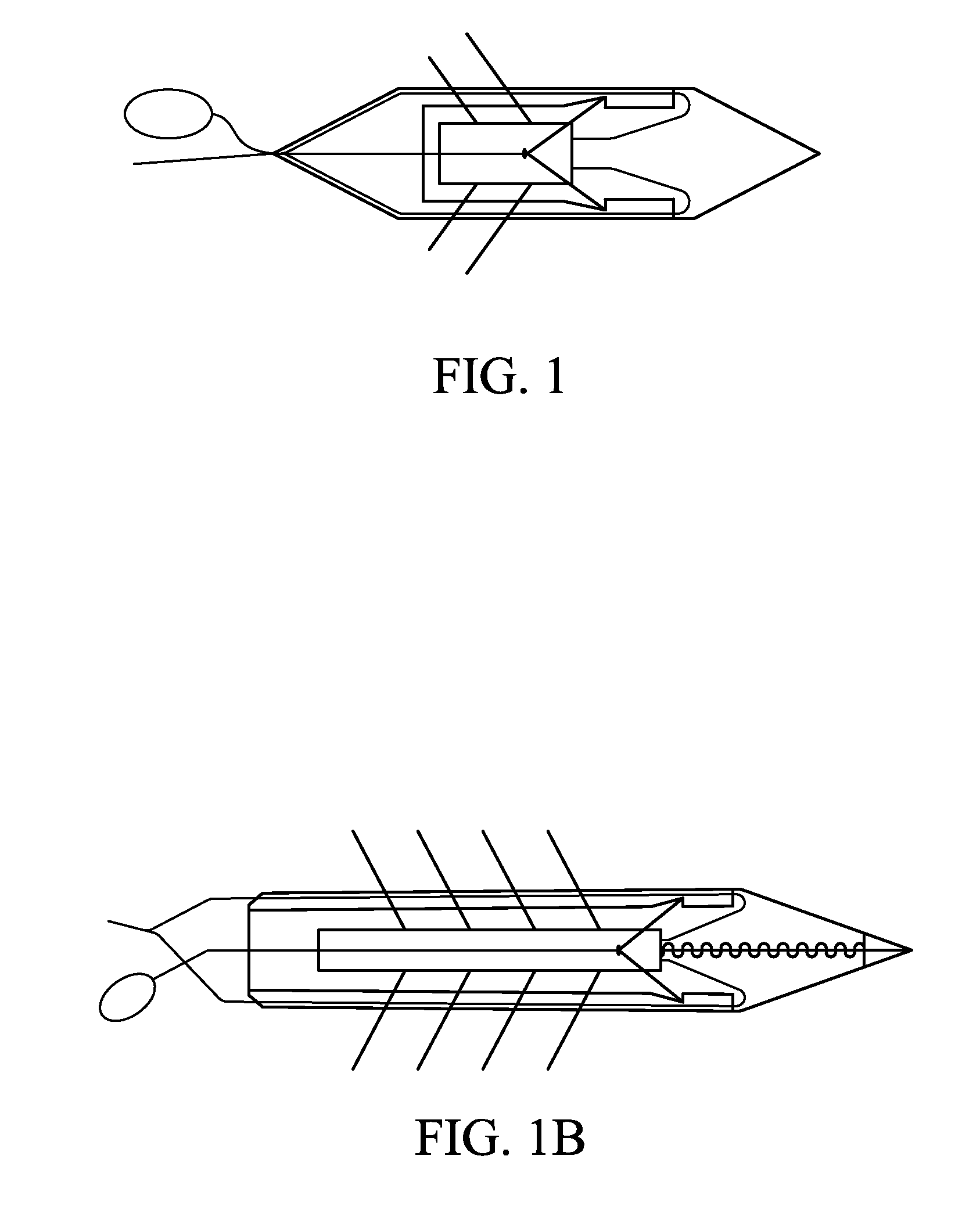
[0051]“Anchors” for the purposes of this application, is defined to mean any fastener. Thus, anchors may comprise C-shaped or semicircular hooks, curved hooks of other shapes, straight hooks, barbed hooks, clips of any kind, T-tags, or any other suitable fastener(s). In one embodiment, anchors may comprise two tips that curve in opposite directions upon deployment, forming two intersecting semi-circles, circle...


PUM


Abstract

This application relates to cardiac medical devices, and specifically to adjustable tensioning devices for tissue anchors, to the intraventricular cardiac anchoring or banding devices themselves, to devices and methods for controlling the depth of penetration of tissue anchors, to devices and methods for the joining of both papillary muscles to the mitral valve, to devices and methods for non-invasive “sling” or “loop” tethering of papillary muscles, to devices and methods for establishing suction prior to and during tissue anchor implant, to a double-barreled needle delivery device, and to a method of remodelling the heart muscle by implanting one or more tethers, and then periodically reducing the tether distance over time.

Description

CROSS REFERENCE TO RELATED APPLICATIONS[0001]Not applicable.STATEMENT REGARDING FEDERALLY SPONSORED RESEARCH OR DEVELOPMENT[0002]No federal government funds were used in researching or developing this invention.NAMES OF PARTIES TO A JOINT RESEARCH AGREEMENT[0003]Not applicable.REFERENCE TO A SEQUENCE LISTING[0004]Not applicable.BACKGROUND[0005]1. Field of the Invention[0006]This application relates to cardiac medical devices, and specifically to adjustable tensioning devices for tissue anchors, to the intraventricular cardiac anchoring or banding devices themselves, to devices and methods for controlling the depth of penetration of tissue anchors, to devices and methods for the triple joining of both papillary muscles to the mitral valve, to devices and methods for non-invasive “sling” or “loop” tethering of papillary muscles, to devices and methods for establishing suction prior to and during tissue anchor implant, to a double-barreled needle delivery device, and to a method of rem...

Claims


Application Information

Patent Timeline
IPC IPC(8): A61F2/04
CPCA61B17/0401A61B2017/00867A61B2017/0412A61F2250/0007A61B2017/0496A61F2/2487A61F2002/3055A61B2017/0427
Inventor FRANCO, JEFF
Owner TENDYNE HLDG
Learn More