Process and materials for making contained layers and devices made with same

a technology of containment layer and process, applied in the direction of thermoelectric devices, chemical instruments and processes, coatings, etc., can solve the problems of reducing the available emissive area of the pixel, affecting the quality of practical containment structures, and requiring certain modifications to achieve full-color displays.

Active Publication Date: 2011-01-27
LG CHEM LTD
View PDF94 Cites 21 Cited by
  • Summary
  • Abstract
  • Description
  • Claims
  • Application Information

AI Technical Summary

Benefits of technology

[0022]developing the priming layer to effectively remove the priming layer from either the exposed areas or the unexposed areas resulting in a first active org

Problems solved by technology

However, manufacture of full-color displays requires certain modifications to procedures used in manufacture of monochromatic displays.
Due to limited space on the display (especially high-resolution displays) this reduces the available emissive area of the pixel.
Practical containment structures generally have a negative im

Method used


Image

  • Process and materials for making contained layers and devices made with same
  • Process and materials for making contained layers and devices made with same
  • Process and materials for making contained layers and devices made with same

Examples


examples

[0162]The concepts described herein will be further described in the following examples, which do not limit the scope of the invention described in the claims.

[0163]In the examples, the following priming materials were used:

[0164]PM-8 through PM-12 are well known compounds. The preparation compound such as PM-1 and PM-4 has been previously described in published PCT application WO 2009 / 067419. The preparation of compounds such as PM-2, PM-3, and PM-6 has been described in published PCT applications WO 2008 / 024378 and WO 2008 / 024379. The preparation of compounds such as PM-7 has been described in published US patent application 2005-0187411.

[0165]Deuterated priming material PM-13 can be prepared as follows.

Synthesis of Compound 2

[0166]

[0167]Under an atmosphere of nitrogen, a 250 mL round bottom was charged with 9,9-dioctyl-2,7-dibromofluorene (25.0 g, 45.58 mmol), phenylboronic acid (12.23 g, 100.28 mmol), Pd2(dba)3 (0.42 g, 0.46 mmol), PtBu3 (0.22 g, 1.09 mmol) and 100 mL toluene. T...

examples 1-10

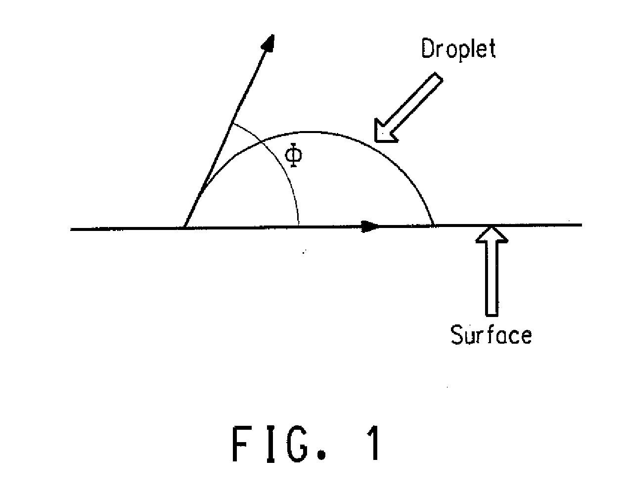
[0179]These examples illustrate different priming materials and the resulting change in contact angle, where the priming layer is formed by liquid deposition and developed by treatment with a liquid.

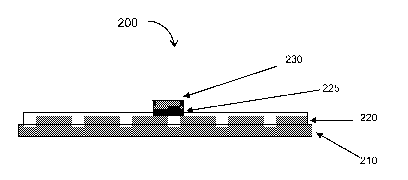
[0180]Test coupons were prepared by spin-coating an aqueous dispersion of HIJ-1 or HIJ-2 onto a glass substrate to a thickness of 50 nm. After drying this layer, a priming layer was formed by spin coating a solution of the priming material onto the dried HIJ layer. In Examples 1-8 and 10, the priming material was spin coated from toluene. In Example 9, the priming material was spin coated from dichloromethane. After drying, the priming layer was exposed to radiation in a pattern. In Examples 1-6 and 8-9, the exposure was at 248 nm with a dosage of 100 mJ / cm2. In Example 7, the exposure dosage was 200 mJ / cm2. In Example 10, there were multiple exposures: 248 nm (1 J / cm2), 365 nm (13 J / cm2), 405 nm (3 J / cm2), and 436 nm (8 J / cm2). After exposure, the priming layer was developed by treatmen...

examples 11-12

[0181]These examples illustrate different priming materials and the resulting change in contact angle, where the priming layer is formed by vapor deposition and developed by heating.

[0182]The test coupons were prepared by depositing HIJ-1 onto a glass substrate as described above. The priming layer was then formed by vapor depositing the priming material in a thermal evaporator. The priming layer was then exposed and developed by baking. In Example 11, the exposure was at 248 nm with a dosage of 400 mJ / cm2. The coupon was developed by baking at 225° C. for 5 minutes. In Example 12, there were multiple exposures: 248 nm (1 J / cm2), 365 nm (13 J / cm2), 405 nm (3 J / cm2), and 436 nm (8 J / cm2). The coupon was developed by baking at 275° C. for 5 minutes. A summary of the materials and results is given in Table 2.

TABLE 2Test Coupon ResultsContact Angle withPrimingMethyl BenzoateExampleLayerExposedUnexposed11PM-1153°12PM-1220°56°


PUM


Abstract

There is provided a process for forming a contained second layer over a first layer, including the steps:
    • forming the first layer having a first surface energy;
    • treating the first layer with a priming layer;
    • exposing the priming layer patternwise with radiation resulting in exposed areas and unexposed areas;
    • developing the priming layer to effectively remove the priming layer from either the exposed areas or the unexposed areas resulting in a first layer having a pattern of priming layer, wherein the pattern of priming layer has a second surface energy that is higher than the first surface energy; and
    • forming the second layer by liquid depositions on the pattern of priming layer on the first layer.
There is also provided an organic electronic device made by the process.

Description

RELATED APPLICATION DATA[0001]This application claims priority under 35 U.S.C. §119(e) from U.S. Provisional Application No. 61 / 228,689 filed on Jul. 27, 2009, which is incorporated by reference herein in its entirety.BACKGROUND INFORMATION[0002]1. Field of the Disclosure[0003]This disclosure relates in general to a process for making an electronic device. It further relates to the device made by the process.[0004]2. Description of the Related Art[0005]Electronic devices utilizing organic active materials are present in many different kinds of electronic equipment. In such devices, an organic active layer is sandwiched between two electrodes.[0006]One type of electronic device is an organic light emitting diode (OLED). OLEDs are promising for display applications due to their high power-conversion efficiency and low processing costs. Such displays are especially promising for battery-powered, portable electronic devices, including cell-phones, personal digital assistants, handheld p...

Claims


Application Information

Patent Timeline
IPC IPC(8): H01L51/00H01L21/04H01L51/50
CPCH01L51/0004H01L51/0012H01L51/52B05D3/06H01L51/56H10K71/13H10K71/191H10K71/00B32B37/0076B32B37/0084B32B37/02B32B37/12B32B37/1284B32B37/1292B32B38/08B32B38/14B32B39/00H10K50/80H10K71/10
Inventor FENNIMORE, ADAMZIEBARTH, JONATHAN M.RADU, NORA SABINA
Owner LG CHEM LTD
Why Eureka
Try Eureka