
Egr cooler bypass strategy

a technology of exhaust gas recirculation and bypass strategy, which is applied in the direction of mechanical equipment, machines/engines, electrical control, etc., can solve the problems of egr coolers being less efficient, catalysts and/or filters in egr ducts presenting additional costs and additional system complexity, so as to avoid the high level of unburned fuel and buildup

Active Publication Date: 2011-02-03
FORD GLOBAL TECH LLC
View PDF11 Cites 19 Cited by
  • Summary
  • Abstract
  • Description
  • Claims
  • Application Information

AI Technical Summary

Benefits of technology

[0008]An advantage according to the disclosure is that the EGR cooler performance can be maintained without providing an oxidation catalyst and / or a diesel particulate filter in the EGR duct.
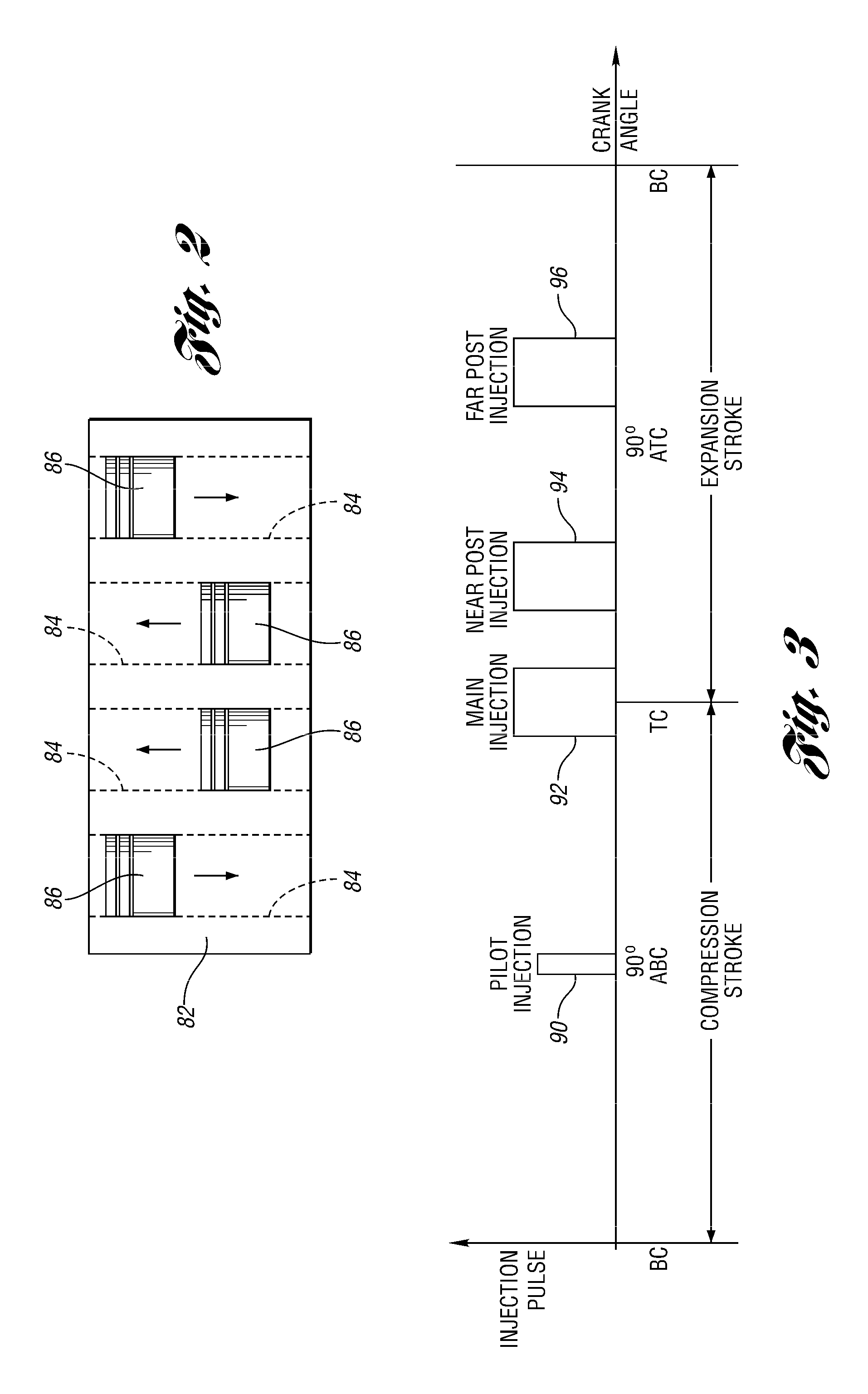
[0009]The engine conditions leading to rapid deposit buildup in the EGR cooler are: idle, off-idle, exhaust system warm up, DPF regeneration, and other engine operating conditions when a post-injection is used and the EGR temperature is less than a temperature threshold. The present disclosure recognizes that these conditions are generally associated with temperature of the EGR gases being below a fuel condensation threshold and a higher concentration of unoxidized or partially oxidized fuel in the EGR gases. It has been found that the unburned fuel forms a coating on the EGR cooler surfaces. During subsequent operation, the coating attracts soot. Successive repetitions of these processes builds layer upon layer. The buildup is prevented by avoiding the high level of unburned fuel from entering the EGR cooler when the EGR gas temperature is lower than the fuel condensation temperature.

Problems solved by technology

Deposits form on the interior surfaces of the EGR cooler, first causing the EGR cooler to be less efficient and finally leading to plugging of the EGR cooler.
The requirement of a catalyst and / or filter in the EGR duct presents an additional cost and additional system complexity.
In addition, EGR catalysts / filters provide a flow restriction that may adversely impact the available EGR flow rate.
However, the prior art fails to recognize other conditions that contribute to accelerated fouling or plugging of an EGR cooler, particularly those associated with fuel condensation.
It has been found that certain engine operating conditions are predominantly responsible for fouling the EGR cooler.
During subsequent operation, the coating attracts soot.

Method used


Image

  • Egr cooler bypass strategy
  • Egr cooler bypass strategy
  • Egr cooler bypass strategy

Examples


Embodiment Construction

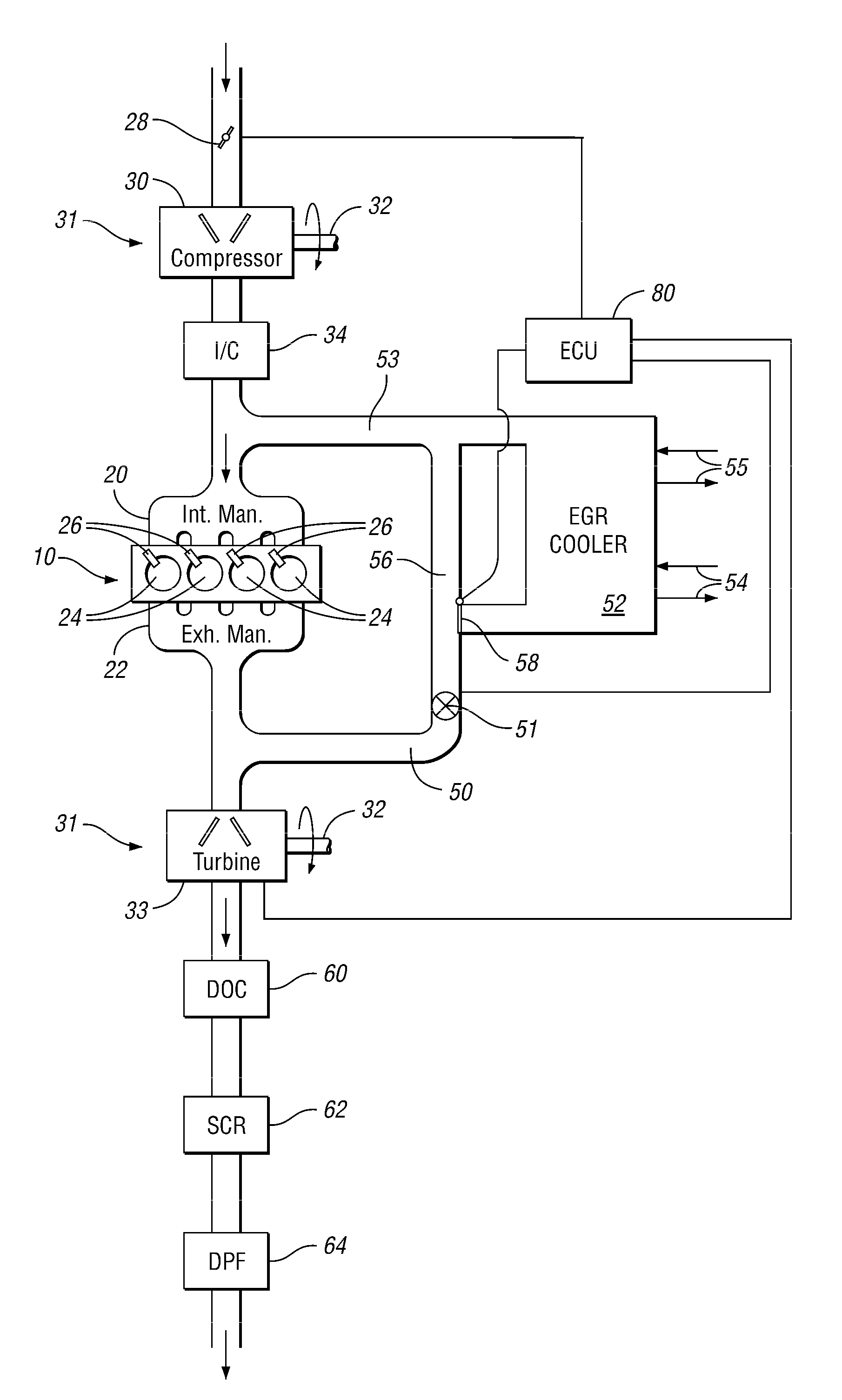
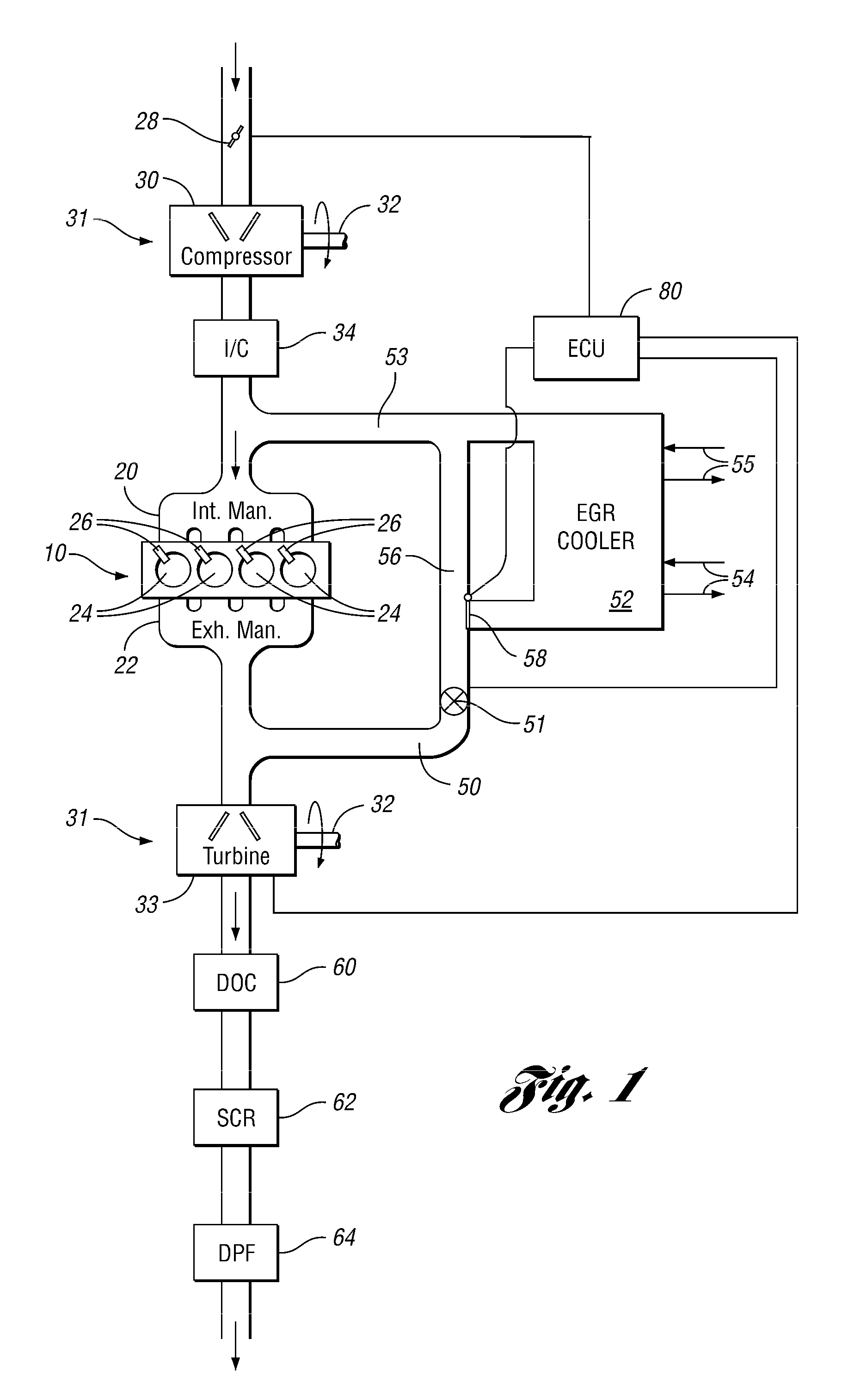
[0014]As those of ordinary skill in the art will understand, various features of the embodiments illustrated and described with reference to any one of the Figures may be combined with features illustrated in one or more other Figures to produce alternative embodiments that are not explicitly illustrated or described. The combinations of features illustrated provide representative embodiments for typical applications. However, various combinations and modifications of the features consistent with the teachings of the present disclosure may be desired for particular applications or implementations. The representative embodiments used in the illustrations relate generally to configurations for aftertreatment and EGR systems for a turbocharged, diesel engine. Those of ordinary skill in the art may recognize similar applications or implementations consistent with the present disclosure, e.g., ones in which components are arranged in a slightly different order than shown in the embodimen...


PUM


Abstract

A system and method for controlling an engine control an EGR cooler bypass valve to divert at least a portion of EGR flow around an EGR cooler when operating under cooler fouling / plugging conditions, such as during idle, off-idle, exhaust system warm up and DPF regeneration or other post injection operation with EGR gas temperature below a corresponding threshold or with EGR low-temperature coolant temperature below a corresponding threshold. The system and method reduce exhaust gases passing through the EGR cooler that contain a high concentration of unburned or partially unburned fuel when the temperature in the EGR system is lower than the fuel condensation temperature.

Description

BACKGROUND[0001]1. Technical Field[0002]The present disclosure relates to exhaust gas recirculation (EGR) systems having EGR coolers and preventing fouling of the EGR cooler by bypassing flow around the EGR cooler.[0003]2. Background Art[0004]One known approach to reduce the amount of NOx produced during combustion in an internal combustion engine is to mix in exhaust gases with the fresh air, commonly called exhaust gas recirculation (EGR). In diesel engines, very high levels of EGR can be tolerated. NOx is further reduced when EGR gases are cooled in the EGR loop, as NOx formation is highly sensitive to temperature. EGR cooling also reduces boost required as the EGR gases are more dense. Thus, an EGR cooler (or heat exchanger) is commonly disposed in the EGR duct.[0005]Deposits form on the interior surfaces of the EGR cooler, first causing the EGR cooler to be less efficient and finally leading to plugging of the EGR cooler. To address that problem, EGR catalysts / filters have been...

Claims


Application Information

Patent Timeline
IPC IPC(8): F02M25/07F02B33/44F01N3/02F02B47/08
CPCF02D41/0055F02D41/029F02D41/08Y02T10/121F02M25/0707F02M25/0728F02D41/405F02M26/05F02M26/25
Inventor STYLES, DANIEL JOSEPHCHEN, KEVINIVES, DAVID CURTISKORPICS, FRANK M.OPOLSKY, NORMAN HIAMWEBB, TIMOTHY
Owner FORD GLOBAL TECH LLC
Learn More