Color filter, method for producing the same, and solid-state imaging device

a color filter and solid-state imaging technology, applied in the field of color filters, can solve the problems of conventional photolithographic methods reaching limitations in view of resolving power, film thickness, and inability to obtain desired film thickness in each color pixel, and achieve excellent rectangularity of color pixel, finer pattern, and improved pattern formation limitation

Inactive Publication Date: 2011-02-03
FUJIFILM CORP
View PDF5 Cites 11 Cited by
  • Summary
  • Abstract
  • Description
  • Claims
  • Application Information

AI Technical Summary

Benefits of technology

[0042]The invention may provide a method for producing a color filter, such that pattern formation limitation is improved and a finer pattern may be formed.
[0043]Further, the invention may provide a color filter excellent in rectangularity of a color pixel.
[0044]Further, the invention may provide a solid-state imaging device excellent in color reproducibility.

Problems solved by technology

In the above-mentioned method for producing a conventional color filter by the photolithographic method, as shown in FIG. 24A, a problem is caused that an area 114 with no color pixels formed occurs in an area in which corners of each color pixel come together.
Also, a problem is that a desired film thickness is not obtained in each color pixel.
In addition, a problem is caused that the film thickness of an area in which color pixels contact with each other is not formed as assumed (that is, as shown in FIG. 24B, a spot 116 where a film thickness of color pixels is thin occurs in the vicinity of the boundary line between color pixels).
The studies such as the optimization of mask bias and the improvement of curing efficiency for an exposure light source of a color curable composition have been made as measures against these problems; however, there is a limitation.
A technique of embedding the second color pixel by heat flow (reflow) in heat curing is also known (for example, refer to Patent Documents 5 and 6); however, this technique is a technique which is easily dependent on performance and process conditions of a color curable composition used for forming the second color pixel or later, and the problem is that the heating distribution of a support is directly reflected in embeddability, for example.
In particular, the micronization of a solid-state imaging device is so remarkable as to require a high-resolution technique for less than 2.0 μm; however, the conventional photolithographic method is reaching a limitation in view of resolving power.
Thus, the above-mentioned problems of the photolithographic method become increasingly remarkable.
However, a curable composition containing dye is generally inferior to pigment in performance of light resistance, thinner film and ease of modification in transmission spectral characteristics, for example.
In particular, in the case of being used for producing a color filter for a solid-state imaging device, a film thickness of 1.0 μm or less tends to be required, so that a large amount of colorant needs to be added to a curable composition; thus, the problems are that adhesion to a substrate becomes insufficient, sufficient curing is not obtained, dye fades away also in an exposure portion, and pattern forming is remarkably difficult.

Method used


Image

  • Color filter, method for producing the same, and solid-state imaging device
  • Color filter, method for producing the same, and solid-state imaging device
  • Color filter, method for producing the same, and solid-state imaging device

Examples


first exemplary embodiment

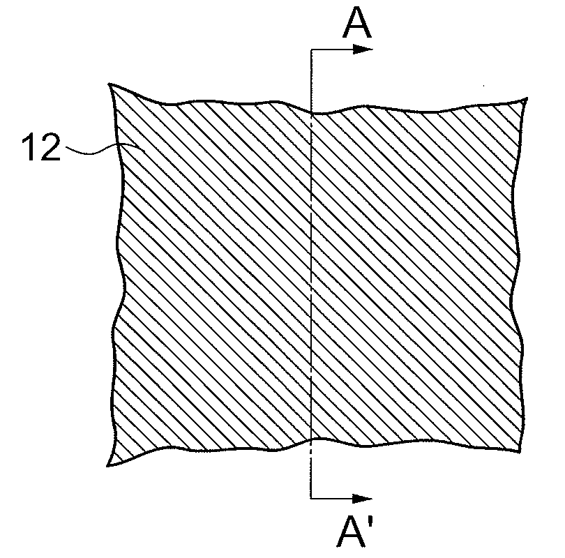
[0194]The first exemplary embodiment is an exemplary embodiment of forming all of the first to the third color patterns by a photolithographic method. The first exemplary embodiment is hereinafter described while referring to FIGS. 1 to 8.

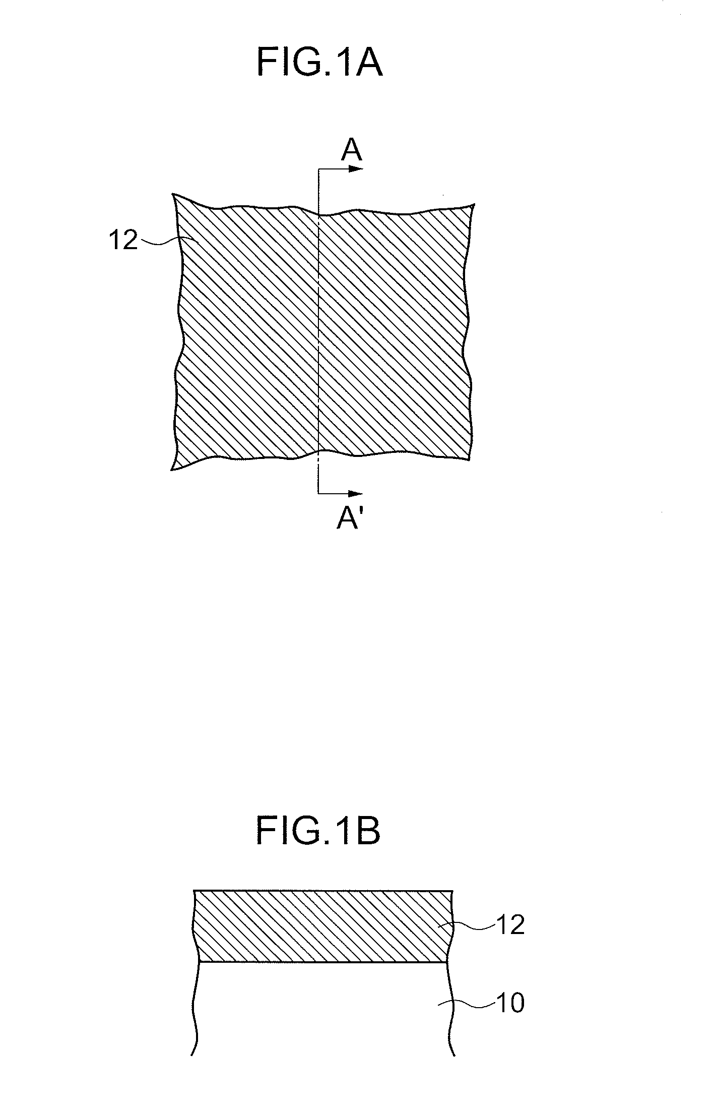
[0195]In FIGS. 1 to 8, A is a plan view and B is an A-A′ line cross-sectional view of A. In FIGS. 4 to 8, C is a B-B′ line cross-sectional view of A.

[0196](The First Color Pattern Forming Step)

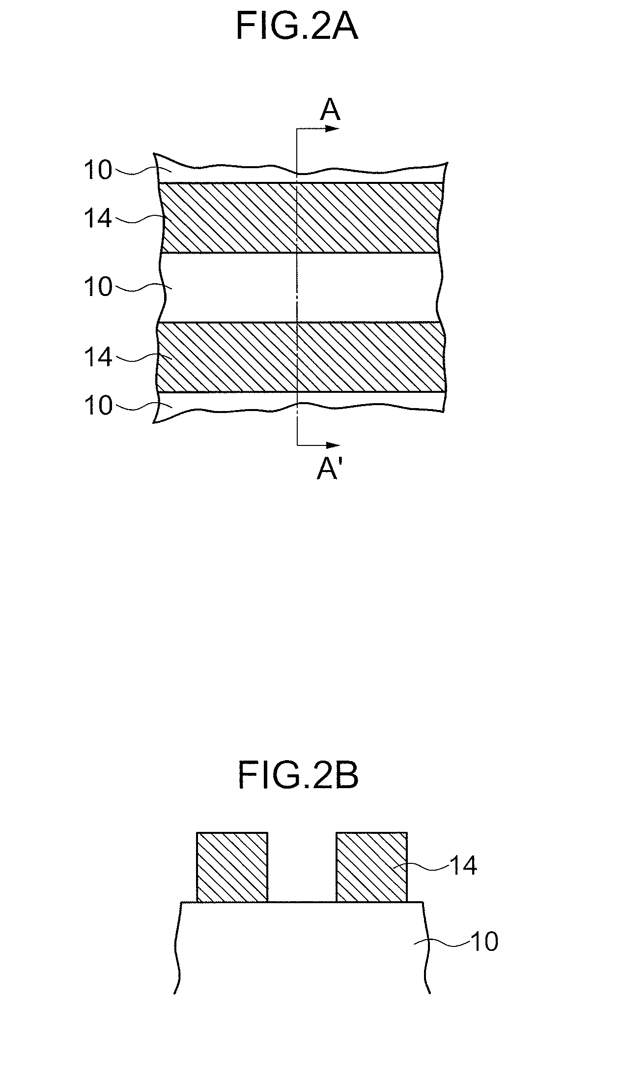
[0197]First, as shown in FIG. 1, for example, a blue pattern material is applied on a support 10 to form a blue color layer 12 as a first color layer into a predetermined film thickness. Thereafter, pattern exposure, development and postbake treatment are performed to form a blue pattern 14, which is a striped pattern as shown in FIG. 2, as a first color pattern.

[0198]Then, in the case that a color filter array is designed as an assembly of square patterns, it is desirable that a pattern width of the blue pattern 14: an interval of the blue pattern 14 (that i...

second exemplary embodiment

[0215]The above-mentioned first and third color patterns may be formed by not merely a photolithographic method but also dry etching (including both the case of forming by the above-mentioned ‘dry etching method’ and the case of forming by the above-mentioned ‘etch back treatment’, and so forth).

[0216]The second exemplary embodiment of forming all of the first to the third color patterns by dry etching is hereinafter described while referring to FIGS. 9 to 18.

[0217]In FIGS. 9 to 18, A is a plan view and B is an A-A′ line cross-sectional view of A. In FIGS. 14 to 18, C is a B-B′ line cross-sectional view of A.

[0218]An exemplary embodiment of having a stopper layer is herein described.

[0219](The First Color Pattern Forming Step)

[0220]As shown in FIG. 9, for example, a red filter material is applied on a support 40 to form a red color layer 42 as a first color layer, and a stopper layer 44 is further formed on the formed red color layer 42 and subjected to baking treatment.

[0221]FIG. 9...

example 1

[0400]A color filter was produced in an exemplary embodiment of forming the first and the third color patterns by a photolithographic method (the first exemplary embodiment). The detailed producing method is hereinafter described.

[0401]

[0402]A blue (B) photocurable composition “trade name: SB-5000L” (manufactured by FUJIFILM Electronic Materials Co., Ltd.) was applied on a silicon substrate into an applied film with a thickness of 0.8 μm by a spin coater, and thereafter prebake treatment was performed at an applied film temperature or an atmospheric temperature of 100° C. for 2 minutes by using a hot plate to obtain a color layer B as a first color layer.

[0403]Subsequently, the color layer B was subjected to pattern exposure at an exposure amount of 200 mJ / cm2 by using an i-ray stepper (manufactured by Canon Inc.) and subjected to development treatment for 1 minute by using developer “trade name: CD-2060” (manufactured by FUJIFILM Electronic Materials Co., Ltd.), and thereafter subj...


PUM

PropertyMeasurementUnit
thicknessaaaaaaaaaa
widthaaaaaaaaaa
widthaaaaaaaaaa

Abstract

A method for producing a color filter in such a manner that a first color pattern is formed in a stripe shape on a support, a second color layer is formed on the support on which the above-mentioned first color pattern has been formed, an area for forming a third color pattern in the above-mentioned first color pattern and / or the above-mentioned second color layer is removed by dry etching, and the third color pattern is formed in the area, from where the above-mentioned first color pattern and the above-mentioned second color layer have been removed, on the above-mentioned support.

Description

TECHNICAL FIELD[0001]The invention relates to a color filter, a method for producing the same, and a solid-state imaging device.[0002]2. Background Art[0003]In recent years, the so-called photolithographic method has been used as a method for producing a color filter from the viewpoint of production costs and ease of production.[0004]The photolithographic method herein is a method for producing a color filter in such a manner that a radiosensitive composition such as a color curable composition is applied and dried on a substrate by a spin coater, a roll coater and the like to form a coating film, which is subjected to pattern exposure, development and baking thereby form a color pixel, and this process is repeated in each color.[0005]The photolithographic method is so high in location accuracy as to be widely utilized as an appropriate method for producing a color filter for a large-screen and high-definition color display.[0006]A technique of using a negative photosensitive compos...

Claims


Application Information

Patent Timeline
Patent Type & Authority Applications(United States)
IPC IPC(8): G02B5/22G03F1/00G02B5/20
CPCG02B5/201G03F7/0007G02B5/286G02B5/223
Inventor YOSHIBAYASHI, MITSUJI
Owner FUJIFILM CORP
Why Eureka
Try Eureka