Thermally-Assisted Magnetic Recording Head Comprising Light Source with Photonic-Band Layer

a technology of photonic band layer and magnetic recording head, which is applied in the field of magnetic recording head, can solve the problems of poor thermal stability of magnetization, the head cannot write data to the magnetic recording medium, and it is difficult for the use of vcsel to meet such a high output power, so as to improve mass-productivity, suppress variation, and high output power

Active Publication Date: 2011-02-03
TDK CORPARATION
View PDF20 Cites 47 Cited by
  • Summary
  • Abstract
  • Description
  • Claims
  • Application Information

AI Technical Summary

Benefits of technology

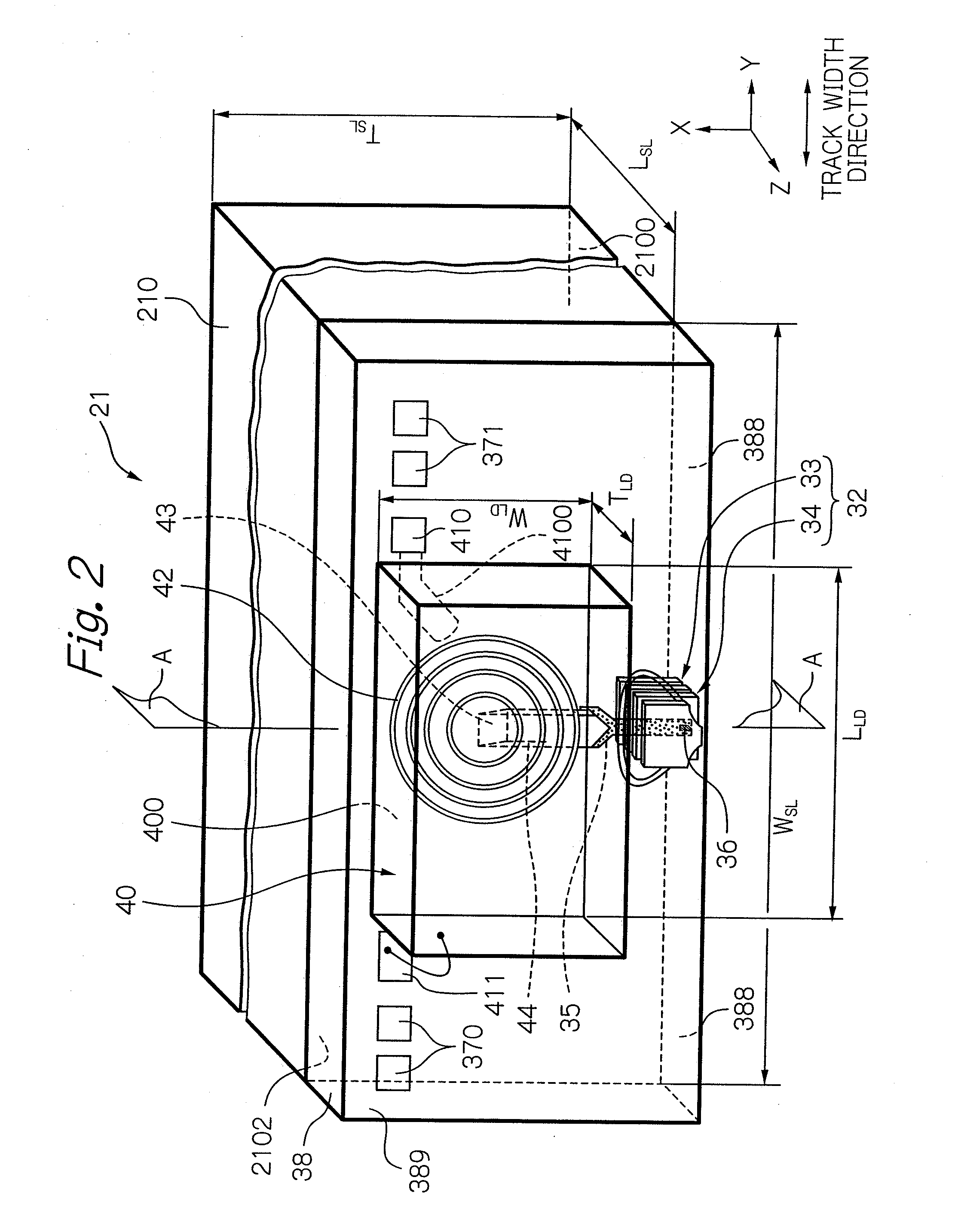
[0023]By structuring the optical system within the head as described above, a light source having a sufficiently high output power can be disposed in the element-integration surface of the slider substrate to achieve improvement of mass-productivity: and based on that, it becomes possible to guide light efficiently into a desired position on the opposed-to-medium surface side without being hardly affected adversely by the change of surrounding temperature.
[0024]Furthermore, the thermally-assisted magnetic recording head according to the present invention preferably further comprises: a light detector that measures an output power of the light source in order to adjust the output power; and at least one detective light-path changer that directs a part of light propagating between the light-emitting surface of the light source and the diffraction optical element toward the light detector. Here, the light source provided within the head according to the present invention can emit a light that is suitable for transforming the light into a light beam with a minute spot size, or is suitable for monitoring the output power of the light, that is, the light source can emit a collimated light with a minute divergence angle. Therefore, by monitoring the light output power of the light source, it becomes possible to suppress the variation due to temperature change and further over time in the light output power, thereby there can be ensured the appropriate heating of the magnetic recording medium. Further, in the configuration including the light detector, the light source and the light detector are preferably provided on an overcoat layer formed on the element-integration surface of the substrate. Furthermore, a part of the diffraction optical element preferably acts as the detective light-path changer.

Problems solved by technology

However, the decrease in size of the magnetic microparticles raises a problem of degradation in thermal stability of the magnetization due to the decrease in volume.
As a result, the head cannot write data to the magnetic recording medium when the anisotropic magnetic field of the medium exceeds the write field limit.
However, from the beginning, more significant problem to be solved exists in how the light is to be supplied from a light source to the inside of a head, and specifically, where and how the light source is to be disposed.
First, as for the insufficient laser output power, the amount of output of near-field light, required for attaining a recording density exceeding 1 Tbits / in2 in a magnetic disk apparatus for performing the thermally-assisted magnetic recording with use of near-field light, has been approximately 1 mW with a spot diameter of 40 nm or less, according to the estimation by the present inventors using simulation and the like. Moreover, the light use efficiency, which the present inventors estimated for the overall optical system in an expected head structure, has been approximately 2%. Therefore, the output power necessary for the laser diode as a light source is estimated to be 50 mW or more. However, a VCSEL generally has a short cavity length, and the output power is about several mW for general use. Therefore, it is difficult for the use of the VCSEL to meet such a high output power.
Therefore, when such a diffraction grating is used, a serious problem may occur such that the function of the diffraction grating is degraded by the wavelength fluctuation and then the laser light may not reach a desired position.
Therefore, for example, it may become difficult to monitor the output of the light emitted from the VCSEL in order to adjust the output.
As a result, the light-path length from the VCSEL to the light detector increases, which may cause greater light loss and prevent satisfactory detection.
Primarily, the considerably large divergence angle of the laser light emitted from the VCSEL has caused a difficulty in transforming the diverged laser light into a light beam with a minute spot size within the head.

Method used


Image

  • Thermally-Assisted Magnetic Recording Head Comprising Light Source with Photonic-Band Layer
  • Thermally-Assisted Magnetic Recording Head Comprising Light Source with Photonic-Band Layer
  • Thermally-Assisted Magnetic Recording Head Comprising Light Source with Photonic-Band Layer

Examples


Embodiment Construction

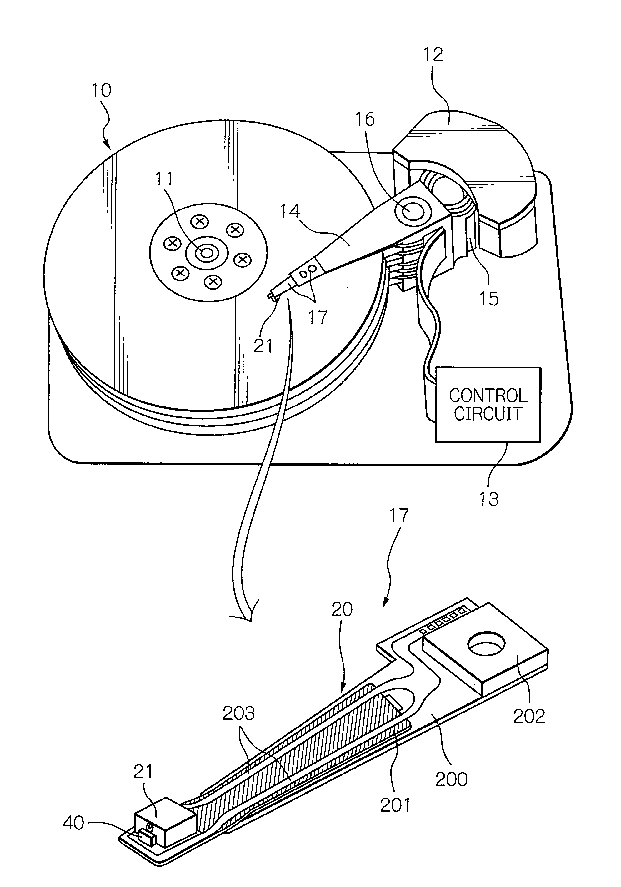
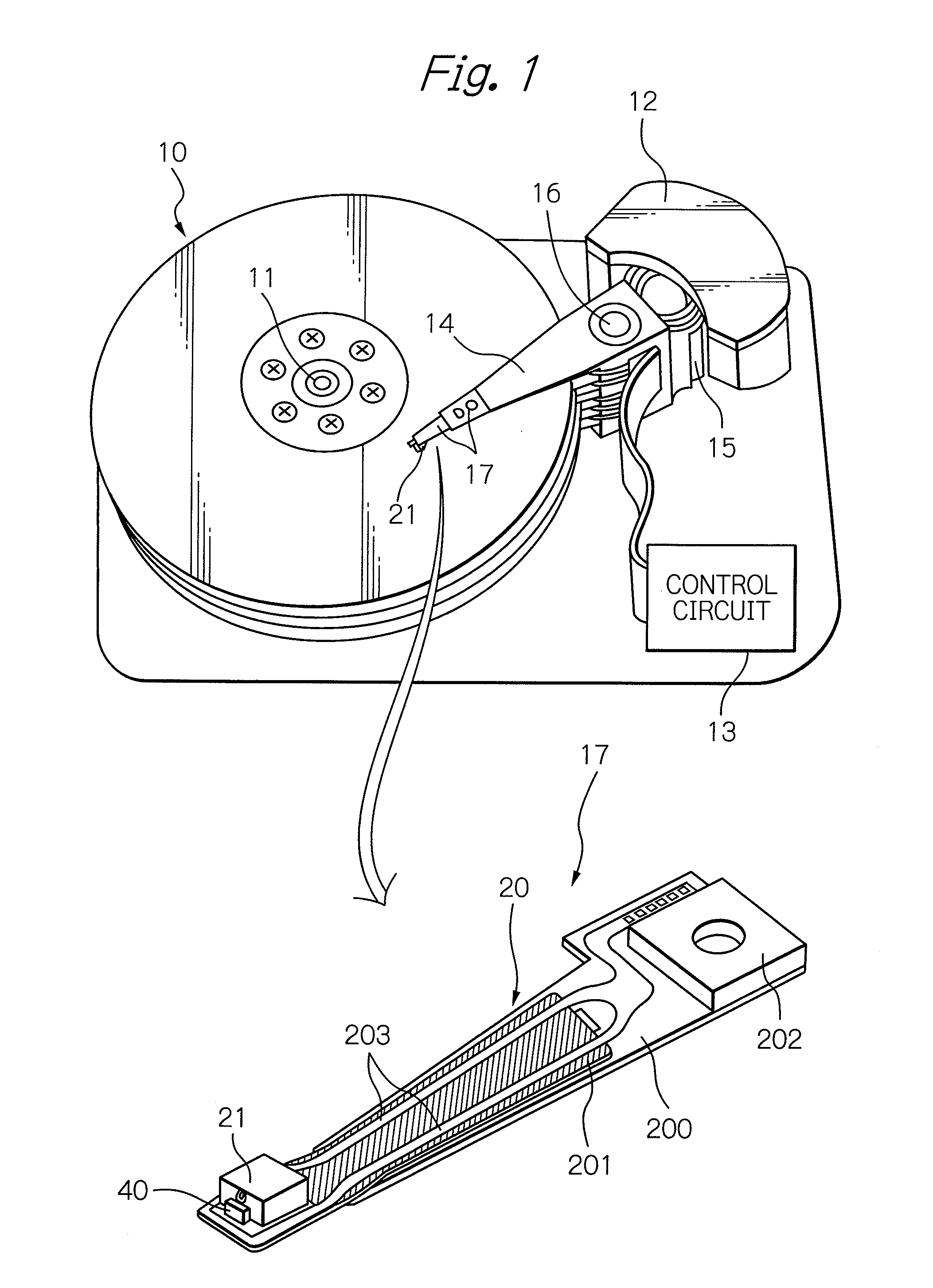
[0045]FIG. 1 shows a perspective view schematically illustrating a structure of a major part in one embodiment of a magnetic recording apparatus and a head gimbal assembly (HGA) according to the present invention. Here, in the perspective view of the HGA, a face of the HGA opposed to the surface of the magnetic recording medium is presented as the upper side.

[0046]A magnetic disk apparatus as a magnetic recording apparatus shown in FIG. 1 includes: a plurality of magnetic disks 10 as magnetic recording media, rotating around a rotational axis of a spindle motor 11; an assembly carriage device 12 provided with a plurality of drive arms 14 thereon; a head gimbal assembly (HGA) 17 attached on the top end portion of each drive arm 14 and provided with a thermally-assisted magnetic recording head 21 as a thin-film magnetic head; and a recording / reproducing and light-emission control circuit 13 for controlling write / read operations of the thermally-assisted magnetic recording head 21 and ...


PUM

PropertyMeasurementUnit
diameteraaaaaaaaaa
diameteraaaaaaaaaa
output poweraaaaaaaaaa

Abstract

A thermally-assisted magnetic recording head is provided, in which a light source having sufficiently high output power for performing thermal-assist is disposed in the element-integration surface of the substrate to achieve improved mass-productivity. The head includes: a light source having a multilayered structure including a photonic-band layer and having a light-emitting surface opposed to the element-integration surface; a diffraction optical element that converges the emitted light; a light-path changer that changes the direction of the converged light; a waveguide that propagates the direction-changed light toward the opposed-to-medium surface; and a magnetic pole that generates write field. The surface-emitting type light source includes a photonic-band layer having a periodic structure in which a light from an active region resonates, and thus emits laser light on a quite different principle from a VCSEL. Therefore, the light source can be disposed in the element-integration surface, even though having sufficiently high output power.

Description

BACKGROUND OF THE INVENTION[0001]1. Field of the Invention[0002]The present invention relates to a magnetic recording head used for thermally-assisted magnetic recording in which a magnetic recording medium is irradiated with light, thereby anisotropic magnetic field of the medium is lowered, thus data can be written. Further, the present invention relates to a head gimbal assembly (HGA) provided with the head, and to a magnetic recording apparatus provided with the HGA.[0003]2. Description of the Related Art[0004]As the recording density of a magnetic recording apparatus, as represented by a magnetic disk apparatus, becomes higher, further improvement has been required in the performance of a thin-film magnetic head and a magnetic recording medium. Especially, in the magnetic recording medium, it is necessary to decrease the size of magnetic microparticles that constitute the magnetic recording layer of the medium, and to reduce irregularity in the boundary of record bit in order t...

Claims


Application Information

Patent Timeline
Patent Type & Authority Applications(United States)
IPC IPC(8): G11B11/00G11B5/02
CPCG11B5/314G11B2005/0021G11B2005/001G11B5/6088
Inventor SHIMAZAWA, KOJITAKAYAMA, SEIICHICHOU, TSUTOMUKOMURA, EIJI
Owner TDK CORPARATION
Why Eureka
Try Eureka