Apparatus comprising a broadcast receiver circuit and provided with an antenna

a technology of broadcast receiver and antenna, which is applied in the direction of electrical equipment, transmission, etc., can solve the problems of internal generated electromagnetic fields, noise, disadvantages of ferrite antennas,

Active Publication Date: 2011-02-03
NXP BV
View PDF18 Cites 241 Cited by
  • Summary
  • Abstract
  • Description
  • Claims
  • Application Information

AI Technical Summary

Benefits of technology

[0009]It is therefore an object of the present invention to provide an apparatus of the type mentioned in the opening paragraph, wherein the reception of signals is less sensitive to changes with the environment and thus less prone to deviations / shifts in the frequency band.
[0025]It has been found most suitably that the coupling from the transmit circuit to the filter circuit is enabled with a capacitor through which RF signal can be transmitted but DC signals are blocked. A capacitor with a capacitance of 0.5 nF or more, for instance 1 nF turns out suitable therefore. In this embodiment, a receive / transmit switch is present between the capacitor and the amplifier and the transmit circuit. A receive / transmit switch is needed to prevent that signals amplified in the transmit circuit directly enter the receive circuit, which is designed for low level signals. This implementation is excellently in line with the desire and need for integration; the receive / transmit switch is designed to be part of an integrated circuit comprising broadcast receiver, the amplifier and the transmit circuit. The capacitor will be a discrete component, or alternatively be integrated within the package. In order to meet requirements of voltage stability, the receive / transmit switch may be implemented as a series connection of a first and a second transistor.
[0026]Suitably, the output impedance of the transmit circuit corresponds to the input impedance of the amplifier. This results in the important characteristic that the current response on the antenna is substantially flat over the broadcast band. This characteristic is more important than the provision of a flat voltage response over the broadcast band. The output impedance is for instance in the range of 20Ω to 2 kΩ. Preferably, the output impedance is relatively low, as a transmit circuit with a larger output impedance draws more power from a battery and less therewith to a degradation of efficiency. A range of 100-50052, particularly 200-40052 turns out optimal, and can be achieved when using a capacitive antenna.

Problems solved by technology

Such ferrite antennas may be disadvantageous in that internally generated electromagnetic fields (e.g. from a central processing unit (CPU), a microcomputer (μC) or the like) are picked up as noise.
Increased miniaturization of audio devices with radio receivers requires smaller ferrites, which leads to undesirable decreases in sensitivity of radio reception.
This decreases the antenna performance.
The decrease in antenna performance is due to reflection.
The decreased transmission of power is problematic, as many radio channels operate at lower field strength than is supposed on the basis of the standardisation for radio channels.
Thus, in short, it is a problem of the use of the headset wire as antenna that the antenna is sensitive to changes with the environment and thus prone to deviations / shifts in the frequency band.

Method used


Image

  • Apparatus comprising a broadcast receiver circuit and provided with an antenna
  • Apparatus comprising a broadcast receiver circuit and provided with an antenna
  • Apparatus comprising a broadcast receiver circuit and provided with an antenna

Examples


second embodiment

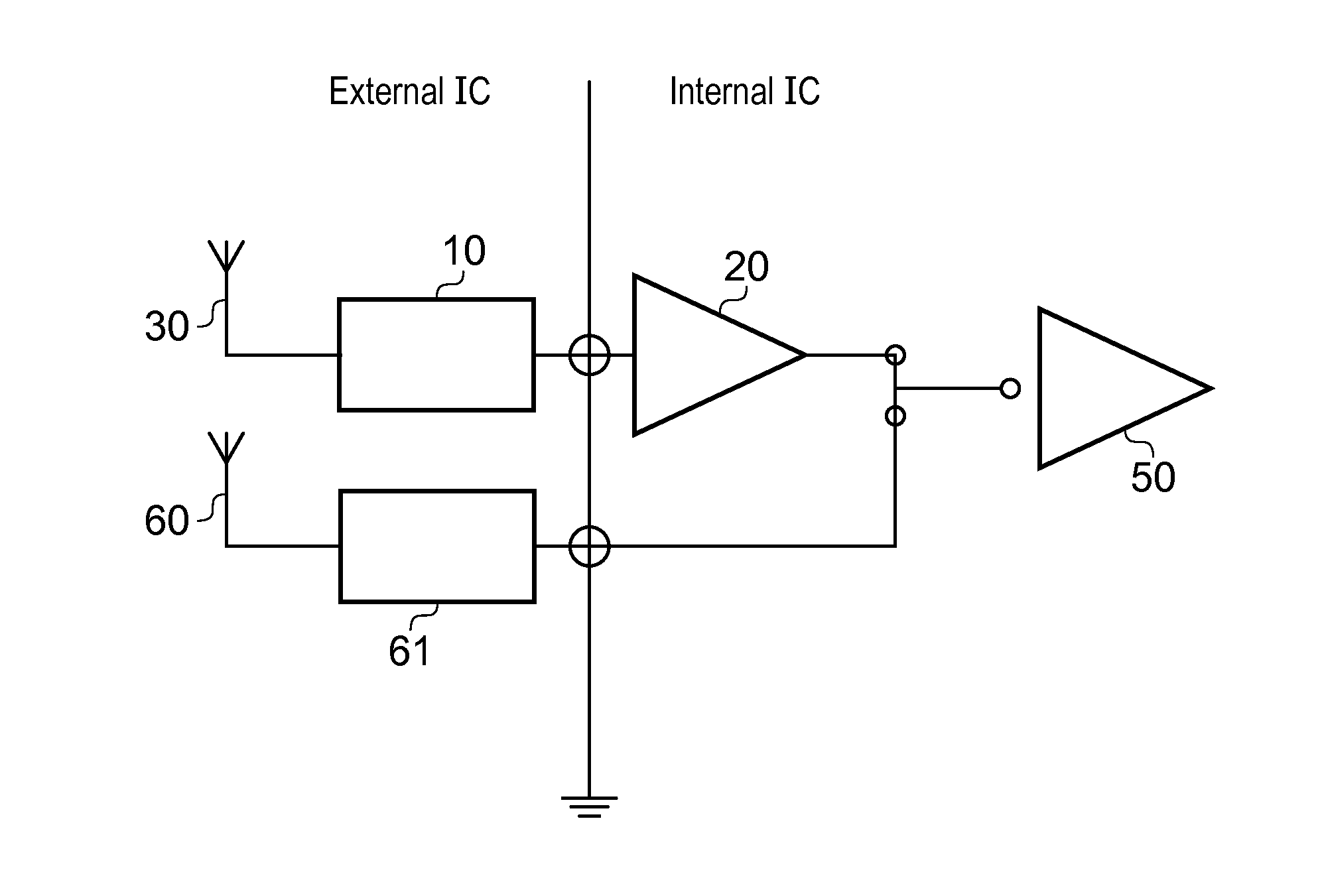
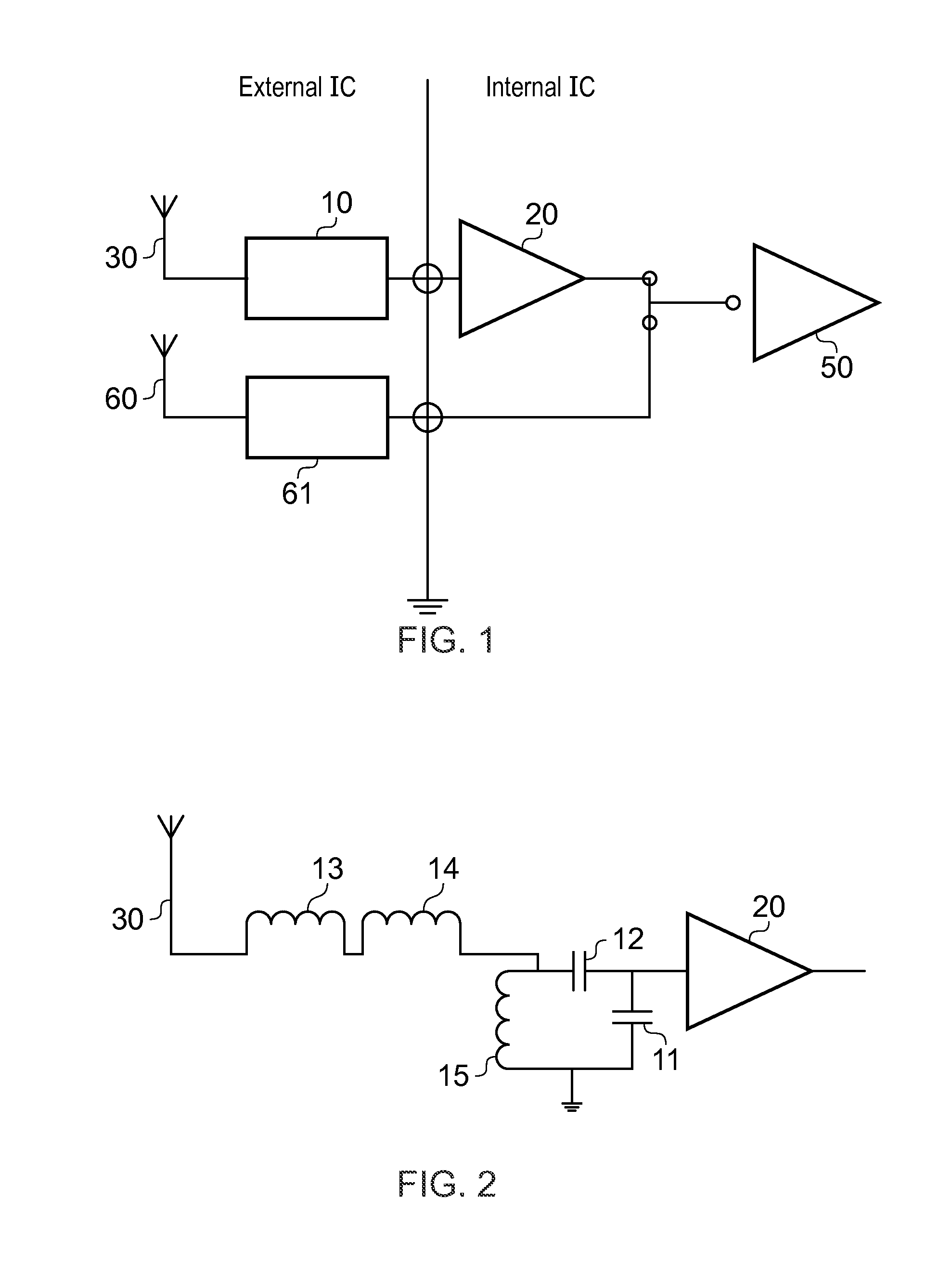
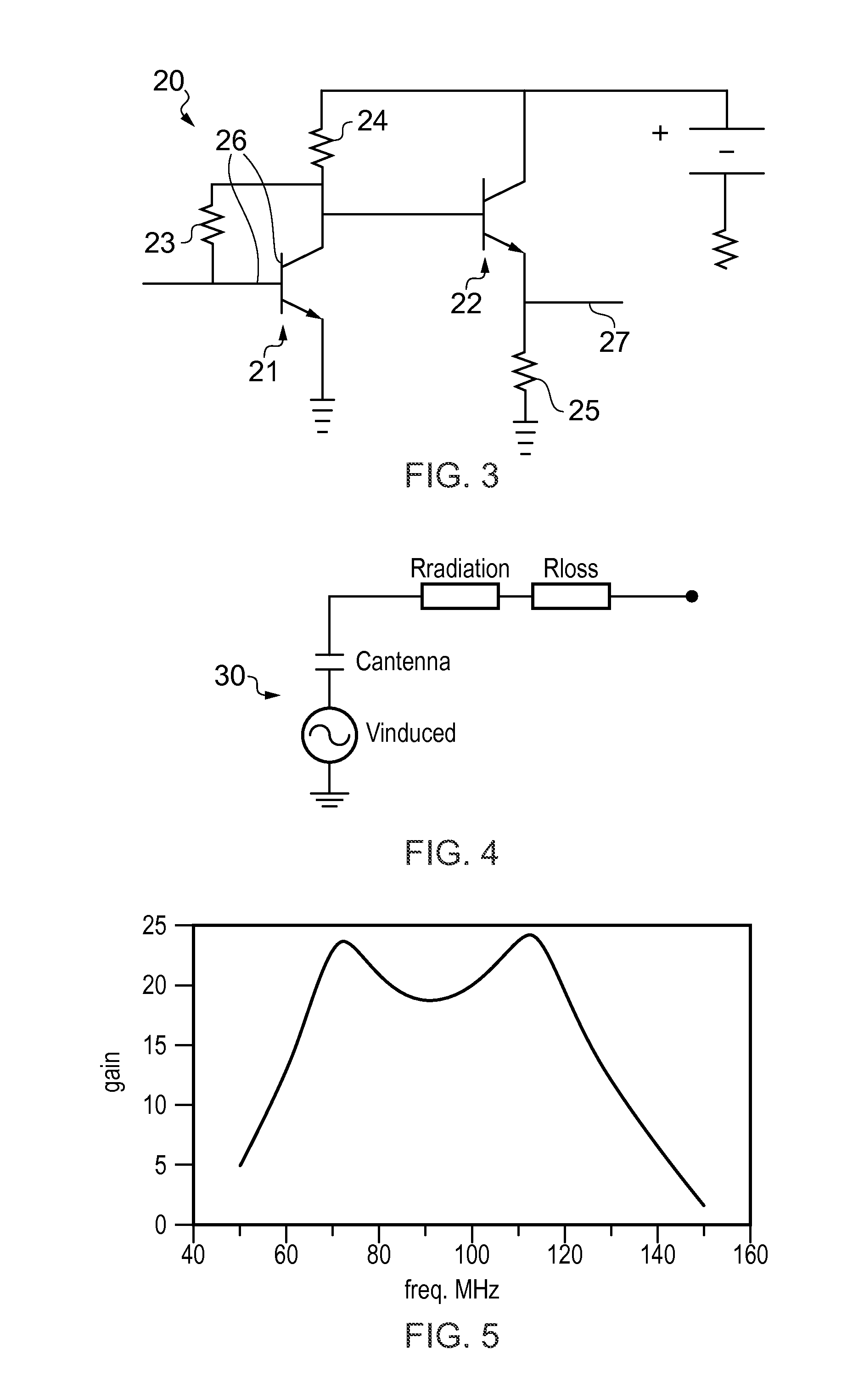
[0060]FIG. 8 shows a schematic of a second embodiment of the system of the invention. This system further comprises a transmit circuit 40. The transmit circuit 40 is coupled the filter circuit 10 over a coupling 41 that is able to reject DC signals, but transmits RF signals. This coupling is for instance achieved with a capacitor 41 of sufficient size, for instance 1 nF or more. In order to combine a transmit circuit 40 and a receiver circuit 50 with a single antenna 30, an receive / transmit switch 42 is needed to prevent that amplified signals from the transmit circuit 40 enter the receiver circuit 50 and particularly the amplifier 20 directly. In a first implementation, a single receive / transmit switch 42 is provided, for instance between the coupling 41 and both of the transmit circuit 40 and the amplifier. In a second implementation, a second receive / transmit switch 43 is present, such that there is one switch 42 between transmit circuit 40 and coupling 41 and one switch between ...


PUM


Abstract

The invention relates to an apparatus 1 comprising a broadcast receiver circuit, an embedded antenna for receiving broadcast signals and a tuning circuit coupled between the antenna and the receiver circuit, which tuning circuit comprises a filter circuit coupled to ground, wherein the tuning circuit is designed to have a first resonance at a first frequency below a broadcast band of interest, and a second resonance at a second frequency above the broadcast band and wherein the tuning circuit comprises an amplifier with an output to the receiver circuit and with an input to the filter circuit, and wherein the tuning circuit is provided with a carrier to noise ratio (CNR) which is substantially fiat across the broadcast band.

Description

FIELD OF THE INVENTION[0001]The invention relates to an apparatus comprising a broadcast receiver circuit and provided with an antenna for receiving broadcast signals and comprising a tuning circuit coupled between the antenna and the receiver circuit.BACKGROUND OF THE INVENTION[0002]In audio devices, radio reception in the AM frequency range is normally achieved by providing an internal ferrite antenna. Such ferrite antennas are configured for a predetermined frequency band in the radio spectrum. The ferrite antenna provides the functions of both an antenna receiving the magnetic part of the electromagnetic wave, and a resonant circuit with an additional capacitance. The first stage of a subsequent antenna amplifier may then have a wide band configuration, while selectivity is obtained in the second amplifier stage.[0003]Such ferrite antennas may be disadvantageous in that internally generated electromagnetic fields (e.g. from a central processing unit (CPU), a microcomputer (μC) o...

Claims


Application Information

Patent Timeline
Patent Type & Authority Applications(United States)
IPC IPC(8): H04B1/10
CPCH04B1/18
Inventor KERSELAERS, ANTHONY
Owner NXP BV
Why Eureka
Try Eureka