
Tough coated hard particles consolidated in a tough matrix material

a technology of hard particles and matrix materials, applied in the field of consolidated materials, can solve the problems of onset of permanent yielding, limiting useful strength, and creating high strength that is not controlled, and achieves the effects of improving transverse rupture strength, reducing the number of sinterings, and maintaining or improving the hardness or other desired properties of conventional sintering tchp materials

Active Publication Date: 2011-02-10
ETERNALOY HLDG GMBH
View PDF5 Cites 47 Cited by
  • Summary
  • Abstract
  • Description
  • Claims
  • Application Information

AI Technical Summary

Benefits of technology

[0014]In some embodiments, the consolidated articles of the present disclosure exhibit higher toughness than an article formed from conventional sintered TCHP that does not comprise a tough matrix. For example, the materials of the present disclosure can exhibit improved transverse rupture strength relative to conventional sintered TCHP, while substantially maintaining or improving the Vickers hardness or other desired properties of conventional sintered TCHP materials. In addition, the inclusion of materials other than TCHP particles such as W, WC, W2C, and Co can provide a significant cost savings, thereby allowing the provision of a hard material with greater strength than conventional TCHP materials, but at reduced cost.

Problems solved by technology

Subjected to increasing load, the material deforms elastically until the dislocations in the grains begin to flow or slip, leading to the onset of permanent yielding and limiting useful strength.
This can result in the creation of high strength that is not controlled by the material between the TCHP particles (if any).
While the transfer of strain fields in conventional sintered TCHP may result in certain improved properties, e.g., strength, it may adversely impact the toughness of the articles formed from such materials.
As a result, articles formed from conventional sintered TCHP can exhibit very high strength, but may exhibit insufficient fracture toughness for some applications.

Method used


Image

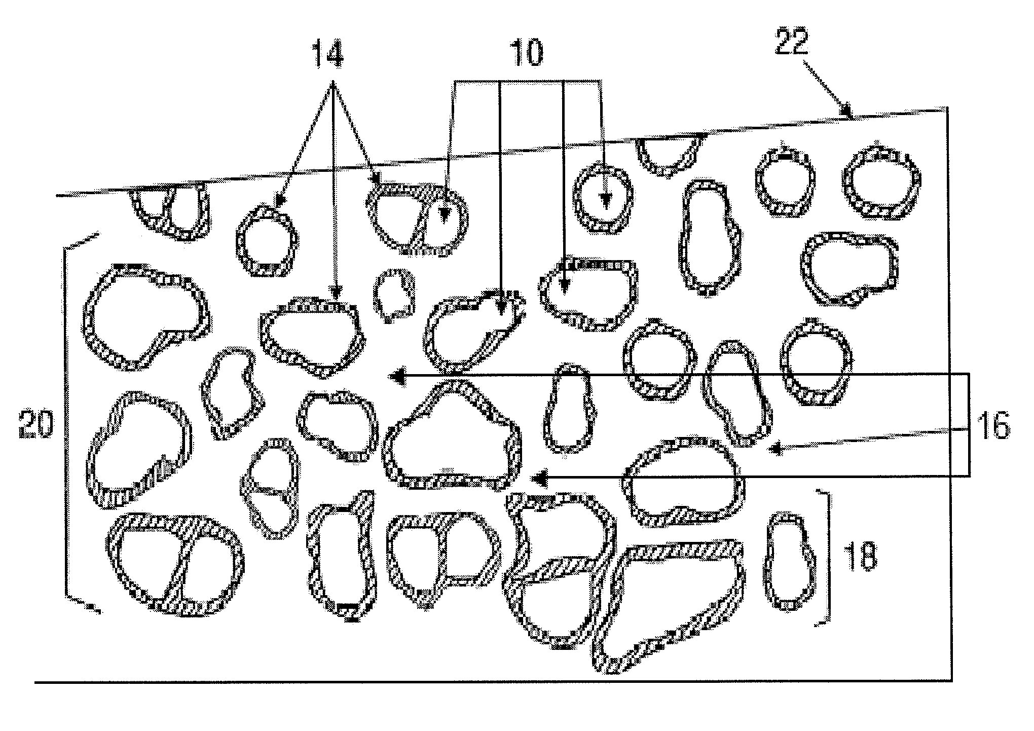
  • Tough coated hard particles consolidated in a tough matrix material
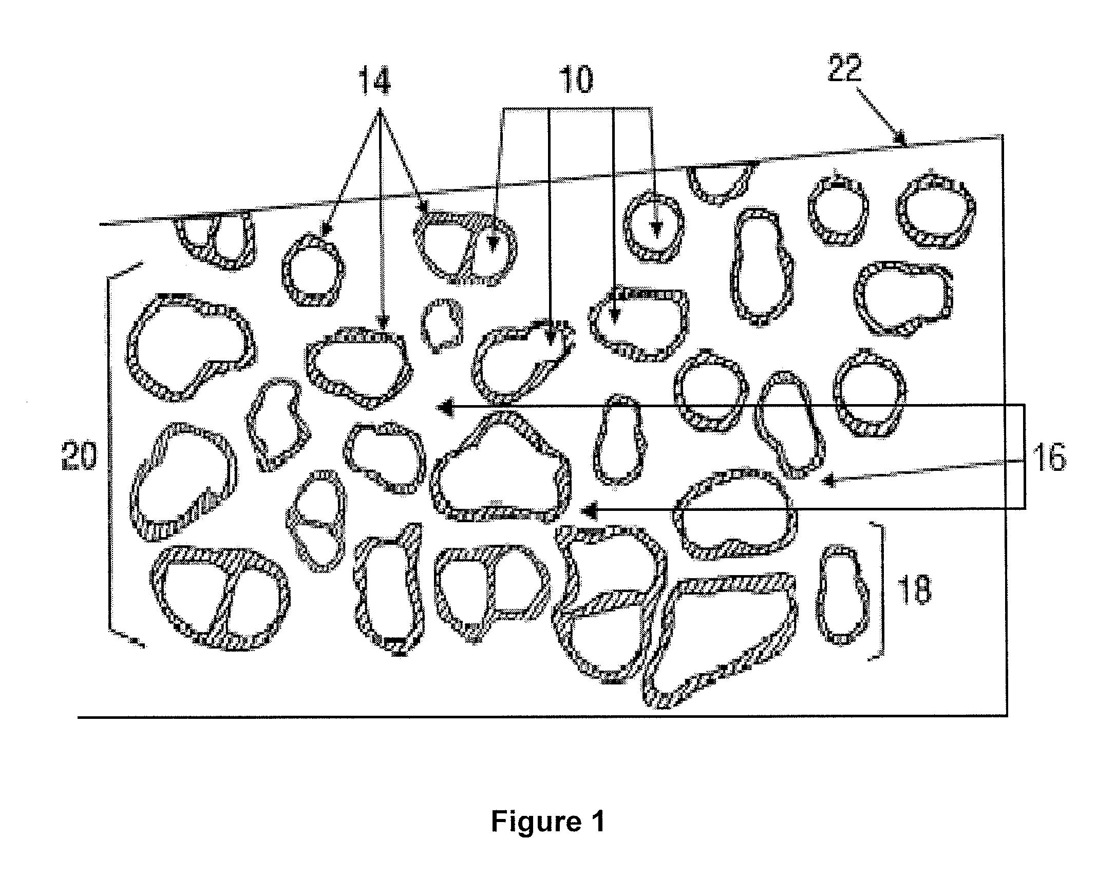
  • Tough coated hard particles consolidated in a tough matrix material
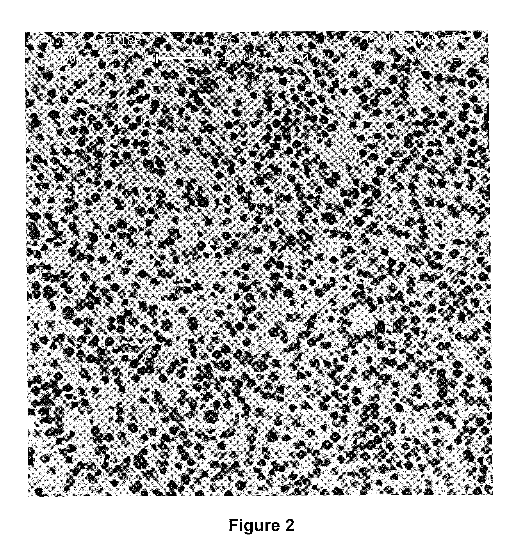
  • Tough coated hard particles consolidated in a tough matrix material

Examples


example 1

Typical Powder Preparation Procedure

[0107]The following is a non limiting example of a powder preparation procedure that was used to prepare a powder in accordance with the present disclosure on a small lab scale basis.

[0108]Using a milling container, the proper proportions of TCHP powder and WC—Co matrix powder were weighed. Generally, the total weight of the powders was about 800 g. Thus, to obtain a powder mixture comprising 25 weight % TCHP and 75 weight % matrix, about 200 g of TCHP and about 600 g of WC—Co matrix powder were used. In some instances, the raw material WC—Co matrix powder contained a small amount (˜2% by weight) of paraffin wax.

[0109]If a waxed powder was desired, an additional 2% of paraffin wax was added to the powder mixture, based on the weight of the TCHP particles. Conversely, if an unwaxed powder was desired, no paraffin wax (beyond the amount present in the raw material powders) was added to the mixture.

[0110]WC—Co milling balls in an amount corresponding...

example 2

Typical Drying Procedure

[0114]The following is a non limiting example of a typical drying procedure for a milled solution of TCHP / WC—Co powder prepared according to Example 1.

[0115]A milled solution of TCHP / WC—Co powder was decanted through a large sized sieve into a temperature resistant vessel (e.g., glass). The milling container used to produce the powder was rinsed with the corresponding solvent (e.g., heptane or ethanol) to remove any remaining milled solution from the WC—Co milling balls.

[0116]The temperature resistant vessel was then placed in a drying oven at a temperature of about 85° C. under a constant nitrogen flow, e.g., of about 2-3 SCFH. The powder was dried for a desired time, e.g., at least 12 hours.

[0117]The powder typically caked together during the drying process. To determine whether the powder was dry, a spatula was used to break apart some of the caked powder. The powder was considered sufficiently dry when the caked powder broke apart into a fine powder.

[0118...

example 3

A First Typical Consolidation Procedure

[0120]The following is a non limiting example of a typical procedure used to produce consolidated articles of the present disclosure via uniaxial hot pressing.

[0121]A mixed, but unwaxed powder including a mixture of TCHP and WC—Co powder was placed into a graphite die set. The die set containing the mixed powder was loaded into the master die of a hot press. The top ram of the hot press was lowered until it came into contact with the top of the die set. The chamber door of the hot press was then closed, and the chamber was evacuated to a minimum pressure of 5.0×10⁻³ torr.

[0122]The hot press was programmed to perform a typical heating cycle, and then switched to automatic control. The mixed powder was then pressed at a specified temperature, at a specified ram pressure, for a specified hold time. The standard parameters used were a temperature of about 1400° C., a pressure of 15 MPa, and a hold time of 100 minutes, although other parameters have...


PUM

PropertyMeasurementUnit
Fractionaaaaaaaaaa
Fractionaaaaaaaaaa
Timeaaaaaaaaaa

Abstract

Consolidated materials comprising a plurality of coated particles dispersed in a tough matrix material are disclosed. The coated particles include a plurality of core particles having an intermediate layer that substantially surrounds each of the core particles. An optional outer layer may be present on the intermediate layer. A matrix contains or substantially contains each of the coated particles, and is formed from at least one third compound including a mixture of W, WC, and / or W2C with Co. The amount of Co in the at least one third compound may range from greater than 0 to about 20 weight %. Methods for providing consolidated materials, and articles comprising such consolidated materials are also disclosed.

Description

[0001]This application claims the priority benefit of U.S. Patent Application No. 61 / 231,149, filed Aug. 4, 2009, the contents of which are hereby incorporated by reference.FIELD OF THE INVENTION[0002]The present disclosure relates to consolidated materials that include coated particles dispersed in a tough matrix. The present disclosure also relates to methods for manufacturing such materials, and articles including such materials.BACKGROUND OF THE INVENTION[0003]Tough coated hard particles (“TCHP” or EternAloy®) are a novel family of particulate materials. Conventionally, TCHP comprise at least one type of superhard, Geldart Class C or larger ceramic and / or refractory alloy core particles having extreme wear resistance, lubricity, and other properties which are individually coated with thin (e.g., nm) layers of a metal compound having a relatively high fracture toughness, such as WC or TaC. In conventional TCHP, an outer coating of a metal, such as Fe, Co or Ni, is provided around...

Claims


Application Information

Patent Timeline
IPC IPC(8): B21C1/00B22F1/18
CPCB22F1/02B22F1/025C04B35/117C04B35/58021C04B35/62831C04B35/645Y10T428/12014C04B2235/3847C04B2235/3856C04B2235/3886C04B2235/96C22C26/00C22C29/02C04B2235/3217B22F1/18C04B35/628
Inventor KEANE, JOHN M.GERMAN, RANDALL M.
Owner ETERNALOY HLDG GMBH
Learn More