
Dye-Sensitized Photoelectric Conversion Device

a photoelectric conversion device and dye sensitization technology, applied in the field of semiconductor fine materials, can solve the problems of not being widely accepted in the market, not being put into practical use, high cost and low supply, etc., and achieve the effect of high conversion efficiency

Inactive Publication Date: 2011-02-10
NIPPON KAYAKU CO LTD
View PDF29 Cites 5 Cited by
  • Summary
  • Abstract
  • Description
  • Claims
  • Application Information

AI Technical Summary

Benefits of technology

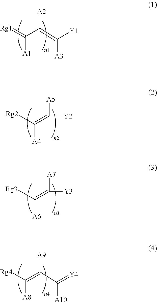
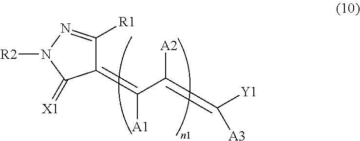
The present invention relates to a photoelectric conversion device that has high conversion efficiency. The invention is based on the use of a specific dye that is sensitized with semiconductor fine materials. The dye has a specific structure and can be bonded to form a ring with certain groups. The device can be used in various applications such as solar cells, light sensors, and image sensors. The technical effect of the invention is to provide a photoelectric conversion device with high conversion efficiency.

Problems solved by technology

However, they have not widely been accepted in the market because of the high production cost and energy-consumingness as well as the difficulties relating to the resources problem.
However, there still lies ahead a problem relating to the material of the sensitizing-dye, for which a ruthenium-type complex, high in cost and low in supply, is used in order to pursue a high conversion efficiency in the device.
Although some attempts have been made to utilize an organic dye for the sensitizing-dye, they have not yet been put into practical use at present due to the difficulties such as low conversion efficiency.

Method used


Image

  • Dye-Sensitized Photoelectric Conversion Device
  • Dye-Sensitized Photoelectric Conversion Device
  • Dye-Sensitized Photoelectric Conversion Device

Examples


synthesis example 1

[0391]Two parts of 1-phenyl-3-carboxy-5-pyrazolone and 1.7 parts of 4-(dimethylamino) benzaldehyde were mixed in 20 parts of ethanol and 0.2 parts of piperazine anhydride were added thereto. The reaction was carried out under reflux for 2 hours. The solid obtained after cooling was filtered, washed, dried, then recrystallized from ethanol and consecutively filtered, washed and dried to give 2.2 parts of compound (I).

[0392]Absorption maximum (ethanol): 506 nm

synthesis example 2

[0393]Two parts of 1-phenyl-3-carboxy-5-pyrazolone and 2 parts of 4-(dimethylamino) cinnamaldehyde were mixed in 20 parts of ethanol and 0.2 parts of piperazine anhydride were added thereto. The reaction was carried out under reflux for 2 hours. The solid obtained after cooling was filtered, washed, dried, then recrystallized from ethanol and consecutively filtered, washed and dried to give 2.3 parts of compound (35).

[0394]Absorption maximum (ethanol): 556 nm

synthesis example 3

[0395]One part of 1-phenyl-3-carboxy-5-pyrazolone and 1.5 parts of 4-(diphenylamino) cinnamaldehyde were mixed in 10 parts of ethanol. The reaction was carried out under reflux for 2 hours. The solid obtained after cooling was filtered, washed, dried, then recrystallized from ethanol and consecutively filtered, washed and dried to give 1.8 parts of compound (36).

[0396]Absorption maximum (ethanol): 506 nm


PUM

PropertyMeasurementUnit
particle diameteraaaaaaaaaa
average primary particle diameteraaaaaaaaaa

Abstract

A photoelectric conversion device using a semiconductor fine material such as a semiconductor fine particle sensitized with a dye carried thereon, characterized in that the dye is a methine type dye having a specific partial structure, for example, a methine type dye having a specific carboxyl-substituted hetero ring on one side of a methine group and an aromatic residue substituted with a dialkylamino group or an organic metal complex residue on the other side of the methine group, or a methine type dye having a carboxyl-substituted aromatic ring on one side of a methine group and a heteroaromatic ring having a dialkylamino group or an organic metal complex residue on the otherside of the methine group; and a solar cell using the photoelectric conversion element. The photoelectric conversion element exhibits a conversion efficiency comparable or superior to that of a conventionally known photoelectric conversion element sensitized with a methine type dye.

Description

[0001]This application is a divisional of U.S. patent application Ser. No. 10 / 482,425 filed Dec. 29, 2003, which is a 371 of PCT / JP02 / 06833 filed Jul. 5, 2002, the disclosures of which are incorporated herein by reference.TECHNICAL FIELD[0002]The present invention relates to a semiconductor fine material sensitized with an organic dye, a photoelectric conversion device and a solar cell, and in particular to an oxide semiconductor fine material sensitized with a dye having a specific structure, a photoelectric conversion device characterized by using the oxide semiconductor fine material and a solar cell using the photoelectric conversion device.BACKGROUND OF THE INVENTION[0003]A solar cell utilizing sunlight as an alternative energy source to a fossil fuel such as petroleum, coal or the like has been paid attention to. Efficiency-enhancement studies have been conducted enthusiastically nowadays for the development and improvement of a silicon solar cell wherein used crystalline or a...

Claims


Application Information

Patent Timeline
Patent Type & Authority Applications(United States)
IPC IPC(8): H01L51/46C09K11/06H01G9/20H01L51/30
CPCH01G9/2031C09B56/08H01L51/0064Y02E10/542C09B23/14C09B23/145Y02E10/549C09B23/0066C09B23/0075C09B23/0091C09B23/04C09B23/06C09B23/083C09B29/081C09B55/002H01G9/2059Y02P70/50H10K85/652C09B56/16
Inventor IKEDA, MASAAKISHIGAKI, KOICHIROINOUE, TERUHISA
Owner NIPPON KAYAKU CO LTD
Learn More