Aircraft with dual flight regimes

Inactive Publication Date: 2011-02-10
ALVAREZ CALDERON F ALBERTO
View PDF10 Cites 48 Cited by
  • Summary
  • Abstract
  • Description
  • Claims
  • Application Information

AI Technical Summary

Benefits of technology

[0013]The present invention solves the problems described above and achieves a double flight regime with fuel efficiency by (a) use of long streamline booms oriented in the flight direction located outboard of the craft's center plane, supported between front and rear wings (b) two side by side rotors of large dimension relative to the weight of the craft mounted on the booms, each of two bladed type, which are counter rotating in planview in vertical and slow speed flight regimes, and therefore are capable of eliminating asymmetric forces on the

Problems solved by technology

As a consequence, its fuel consumption is very high during vertical flight, its range is short, and the time it can operate in vertical flight is very restricted.
On the other hand, the high speed is limited by compressibility effects on the tips of rotors tilted forward for winged flight, and therefore its maximum forward speed is about half that of the Harrier.
Prior efforts to develop aircraft capable of a double flight regime have been attempted in the past, but they have failed in the marketplace.
A single stoppable rotor, or tandem stoppable rotors, proposed for crafts with wings for higher speeds, present formidable problems in transition between rotor supported flight and wing supported flight, because of the large asymmetric forces experienced by the rotors as their rotational speed a

Method used


Image

  • Aircraft with dual flight regimes
  • Aircraft with dual flight regimes
  • Aircraft with dual flight regimes

Examples


first embodiment

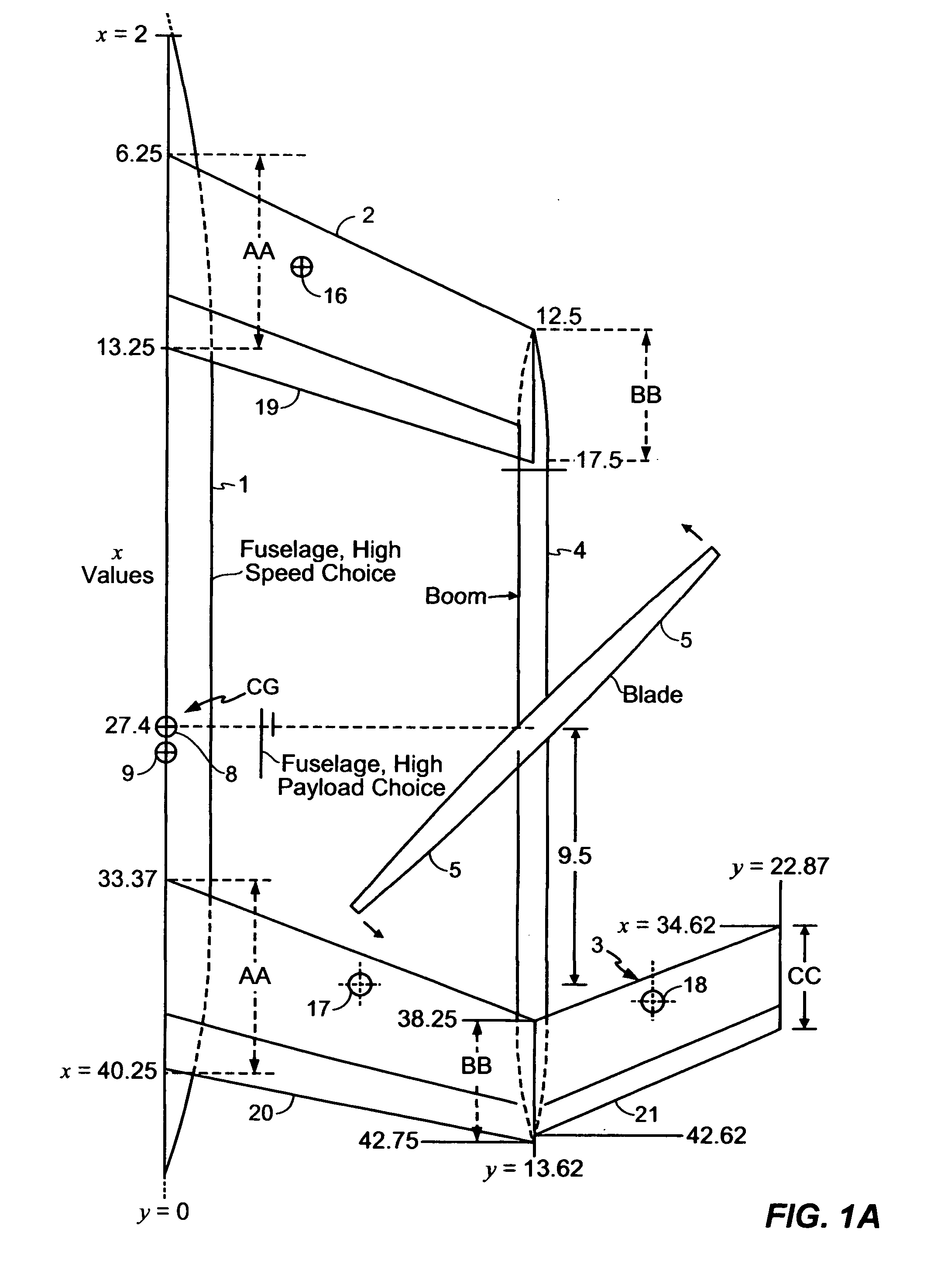
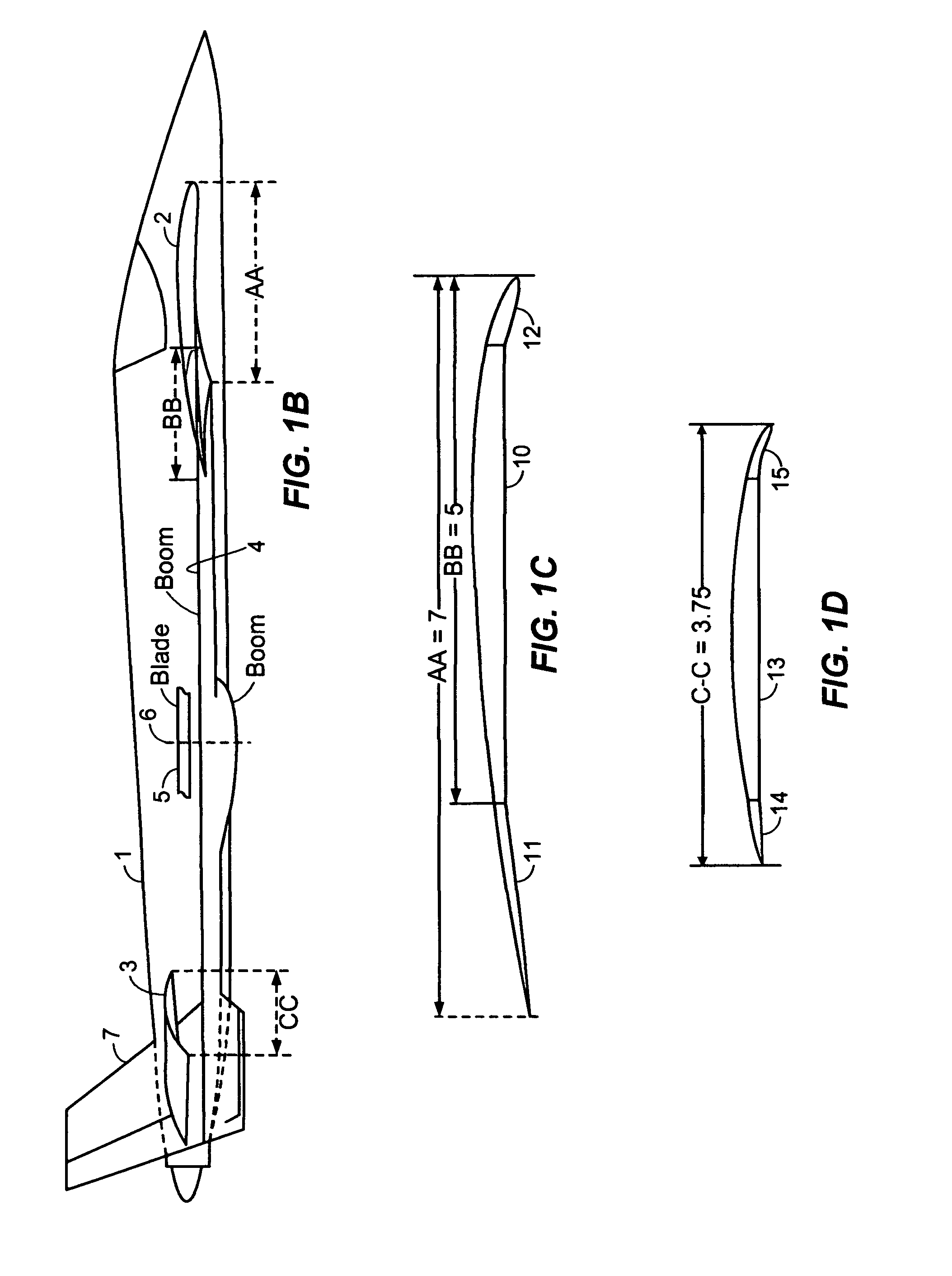
[0022]FIG. 1a shows in top view the right half of my VTOL aircraft, hereafter referred to as VTOL-1, using swept wings. Specifically fuselage 1 supports a front swept-back wing 2 of small span and a rear wing with large span 3 using a W planform. A long right boom 4 extends between the tip of wing 2 and at the change of sweep of wing 3. Boom 4 supports a two bladed rotor 5 that can turn counter clockwise as shown, or clockwise. Fuselage 1 can carry a jet engine, and rotor 5 can be driven by an electric motor installed in the boom, or by an engine which can be cross-shafted to a left engine on a left boom.

[0023]In high speed flight regime, rotor blades 5 are aligned and adjacent to boom 4 for minimum drag. The blades can also be housed inside doors on the booms, as will be shown later on. The swept wings allow the craft to reach speeds of up to approximately MACH 0.85. In slow or vertical flight regime, rotor 5 and its opponents left rotor (not shown) rotate in opposite directions to...

second embodiment

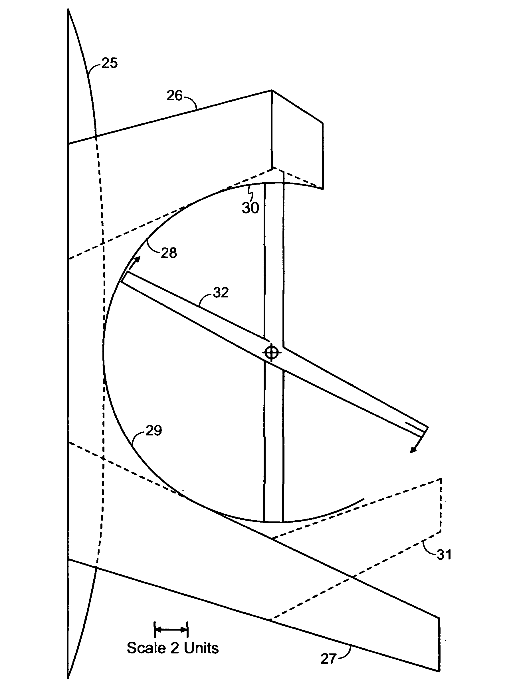
[0045]FIG. 2 shows the invention referred to hereafter as VTOL-2. It is intended to augment rotor lift in vertical flight by surrounding a large portion of the perimeter of its rotors with portion of the wing and fuselage surfaces, such that the reduced pressures (lower than atmospheric) on top of the rotor's plane extends over the adjacent surfaces of the craft, as well as reducing tip losses at the tip of the blades in a large portion of its circumference.

[0046]Specifically, FIG. 2 shows a central fuselage 25, front wing 26 swept forward, and swept back wing 27. In planform the shapes of the central portion of fuselage and the adjacent trailing portion of front of wing 26 combines to form a portion of a ring 28, surrounding part of the circumference of rotor 32. The central portion of fuselage 1 and the root of the leading edge of rear wing 27 combine to form another portion of a ring 29, surrounding part of the circumference of the rotor's circle. When combined, portions 28 and 2...

fourth embodiment

[0048]FIG. 4 shows the invention, described as VTOL-4, the main feature of which is the elimination of the central fuselage shown in FIG. 1. Specifically, the type of swept back wing 38 are joined to portions of wing 39 by left boom 40 and right boom 41. The booms extend from the tip of wing 38 to the portion of wing 39 at which sweepback is reversed to form a W-planform. Two rotors are mounted on the booms shown with their peripheral paths 42 and 43.

[0049]FIG. 5 shows my twin rotor configuration in an embodiment referred to as VTOL-5. It exemplifies firstly a pure helicopter configuration comprising central fuselage 48 with lateral wings or beams 49 and 50 supporting at their tips rotors having tip path 51 for the right rotor and 52 for the left rotor. This configuration offers practical advantages, such as avoiding the need of a tail rotor, or allowing the use of rigid fixed pitch rotor blades, as will be discussed later on. In a variant of FIG. 5 each rotor is asymmetric and has ...


PUM


Abstract

The aircraft is capable of two distinct fuel-efficient flight regimes: one is a vertical flight regime supported by two large two-bladed rotors with low disc loading located on right and left longitudinal booms. The booms extend between outboard regions of a front wing and inboard regions of a rear wing that has a larger span an area. The other flight regime is high speed up to high subsonic Mach number with the aircraft supported by wing lift with high wing loading, and with the rotors stopped and faired with minimal local drag contiguous to the booms. The longitudinal location of the aircrafts center of gravity, aerodynamic center and the center of the rotors are in close proximity. The front wing is preferably swept back, and the rear wing is preferably of W planform.

Description

STATEMENT REGARDING FEDERALLY SPONSORED RESEARCH OR DEVELOPMENT[0001]The present invention has no federally sponsored research and development work and is entirely privately funded.CROSS REFERENCE TO RELATED APPLICATIONS[0002]Provisional Patent Application No. 61 / 217,997 was filed by inventor on Jun. 4, 2009 with specifications for FIGS. 1 to 5 and several claims.COMPACT DISC APPENDIX[0003]A DVD showing flight of remote control model of the invention may be filed by mail (or E-mail) upon receiving a patent application number and filing date of the present application.BACKGROUND OF INVENTION[0004]1. Field of Invention[0005]The present invention pertains to vertical takeoff and landing aircraft (VTOL), also capable of short take off and landing (STOL), with a configuration capable of hovering with low disc loading and winged flight at a mach number near the speed of sound.[0006]2. Prior Art[0007]In the 1960's, and prior to that time, and after that time, various efforts have been cond...

Claims


Application Information

Patent Timeline
IPC IPC(8): B64C27/30B64C27/26B64C27/473
CPCB64C3/10B64C29/0025Y02T50/12B64C39/08B64C29/0033Y02T50/10
Inventor ALVAREZ CALDERON F., ALBERTO
Owner ALVAREZ CALDERON F ALBERTO
Why Eureka
Try Eureka