Control device for controlling travel motor of vehicle

a technology of control device and travel motor, which is applied in the direction of program control, electric energy management, compasses, etc., can solve the problems of reducing the detection reducing the control accuracy of the rotary body such as the travel motor, and reducing the accuracy of the rdc to detect the rotation angle of the travel motor. , to achieve the effect of suppressing the decrease of accuracy, reducing gain, and superior performan

Active Publication Date: 2011-02-10
DENSO CORP
View PDF5 Cites 12 Cited by
  • Summary
  • Abstract
  • Description
  • Claims
  • Application Information

AI Technical Summary

Benefits of technology

[0035]In particular, the RDC in the control device has a gain judgment means and a gain adjustment means. The gain judgment means judges whether or not the travel motor rotates at a constant rotation speed based on the above error deviation ε. The gain adjustment means decreases the gain when the judgment result of the judgment means indicates that the travel motor rotates at a constant rotation speed.
[0036]That is, because the RDC integrates two times the value obtained by multiplying the error deviation ε by the gain in order to obtain the rotation angle output value φ, it can be said that the value “ε×gain” corresponds to the detection value of the acceleration of the electrical angle θ (that is, the angular acceleration). In the control device according to the present invention, the gain adjustment means in the RDC decreases the gain of the error deviation ε in order for the detection value of the angular acceleration to approach zero when detecting that the travel motor rotates at a constant rotation speed based on the error deviation ε. This control process makes it possible to change the rotation angle output value φ to the time elapse as proportional as possible.
[0037]Accordingly, when the ECU as the control device intends to drive the travel motor at a constant rotation speed, even if the resolver outputs a detection signal containing a waveform distortion, it is possible to suppress the decrease of accuracy to detect the rotation angle of the travel motor, and to keep the superior performance to control the operation of the travel motor, and to give a comfortable driving to the passengers and driver of the vehicle.
[0038]Further, the control device according to the present invention does not decrease the gain of the error deviation ε unless the judgment means judges that the travel motor rotates at a constant rotation speed. Accordingly, because the rotation angle output value φ output from the RDC can be changed accurately corresponding to and quickly responding to the acceleration of the travel motor when the control device instructs the travel motor to accelerate, it is possible for the control device according to the present invention to drive the rotation speed of the travel motor with good response.
[0039]In general, when the control device instructs the travel motor to accelerate, the actual acceleration of the travel motor becomes larger than undesirable acceleration caused by a rotation angle detection error. Therefore there is no problem for the passengers and driver of the vehicle to feel uncomfortable driving.

Problems solved by technology

However, the resolver has another problem to have a manufacturing error in shape of the rotor and the stator thereof.
When the resolver outputs the rotation detection signals having a waveform distortion, the RDC does not generate a correct output, and this increases an error component in the rotation angle output value φ output from the RDC (in other words, the detection accuracy of the RDC to detect the rotation angle of the travel motor is decreased), and this decreases the control accuracy of the rotary body such as the travel motor.
The conventional technique disclosed in JP 3365063 does not suppress the deterioration of the rotation detection accuracy caused by the distortion of the output waveform of the resolver.
FIG. 9 is an explanatory view showing a problem caused by a conventional technique when a resolver outputs a detection signal with a waveform distortion.
Because the control device for a travel motor obtains the rotation angle of the drive motor based on the rotation angle output value φ transferred from the RDC and determined the current vector to be supplied to the travel motor, it would be difficult for the control device to output the optimum current vector.
This decreases the accuracy to control the rotation angle of the travel motor.
Further specifically, when the control device for a travel motor instructs the travel motor to rotate at a constant rotation speed in order to drive the vehicle at a constant speed according to the information instructed by the driver of the vehicle such as by the stroke of the accelerator pedal, the control device controls the travel motor to operate based on a different rotation angle which is different from an actual rotation angle of the travel motor by the rotation angle detection error caused by an output waveform distortion from the resolver.
This increases or decreases the output torque of the travel motor, and thereby causes undesired acceleration or deceleration of the vehicle.
This gives uncomfortable driving to the passengers and the driver of the vehicle.

Method used


Image

  • Control device for controlling travel motor of vehicle
  • Control device for controlling travel motor of vehicle
  • Control device for controlling travel motor of vehicle

Examples


first embodiment

[0052]A description will be given of the control device capable of controlling the operation of a travel motor mounted to an electric vehicle according to the first embodiment of the present invention with reference to FIG. 1 to FIG. 5.

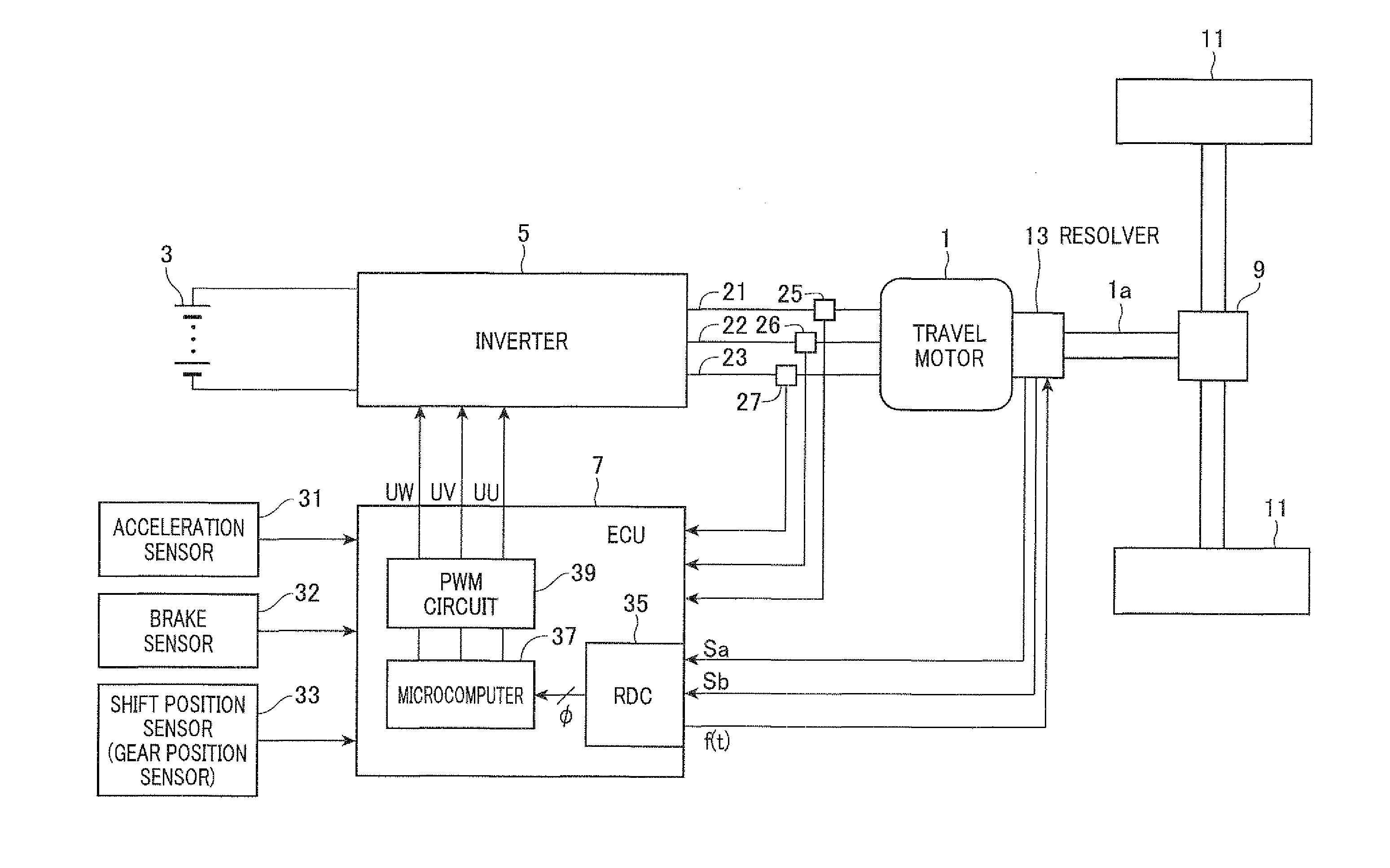
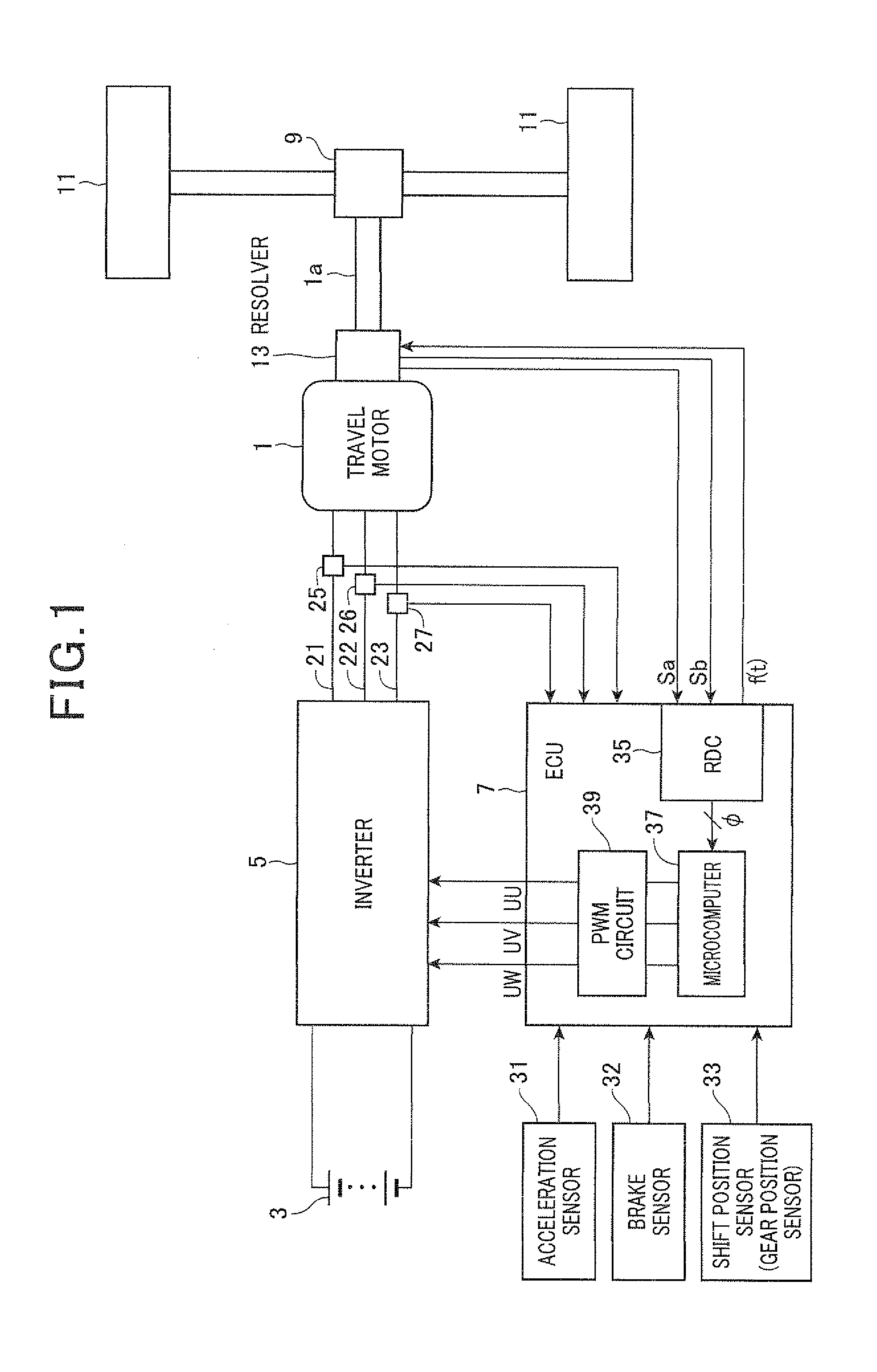
[0053]FIG. 1 is a view showing a circuit configuration of the control system for an electric vehicle comprised of a resolver 13, an inverter 5, a travel motor 1, and an ECU (control device) 7 having an RDC 35 according to the embodiments of the present invention.

[0054]As shown in FIG. 1, the electric vehicle is equipped with the travel motor 1 composed of an AC synchronous motor which is known and available in the commercial markets, a battery 3 which serves as a DC power source, the inverter 5 which is also known device and drives the travel motor 1, and the ECU 7 (control device) which is comprised of a resolver digital converter 35, a microcomputer 37, and a PWM circuit 39. The RDC 35 is capable of controlling the operation of the travel motor 1. A...

second embodiment

[0124]A description will be given of the control device according to the second embodiment of the present invention with reference to FIG. 6.

[0125]FIG. 6 is a flow chart showing the process to detect the rotation state of the travel motor 1 performed by the gain control part 53 in the RDC 35 of the ECU 7 according to a second embodiment of the present invention.

[0126]When compared with the process to detect the rotation state of the travel motor 1 performed by the gain control part 53 in the RDC 35 of the ECU 7 according to the first embodiment, the gain control part 53 according to the second embodiment performs the process to detect the rotation state of the travel motor 1 shown in FIG. 6 every updating the output of the multiplier 49.

[0127]As shown in FIG. 6, the gain control part 53 increments a counter Ca by 1 (step S320) when the multiplier 49 outputs a positive output value (=ε·Ka) (“YES” in step S310). On the other hand, the gain control part 53 increments a counter Cb by 1 ...

third embodiment

[0134]A description will be given of the ECU 7 as the control device according to the third embodiment of the present invention with reference to FIG. 7. FIG. 7 is a flow chart showing the process to detect the rotation state of the travel motor 1 performed by the gain control part 53 in the RDC 35 of the ECU 7 as the control device according to the third embodiment of the present invention. When compared with the configuration of the ECU 7 according to the first embodiment, the gain control part 53 in the RDC 35 in the ECU 7 according to the third embodiment performs the process to detect the rotation state of the travel motor 1 shown in FIG. 7 instead of the process to detect the rotation state of the travel motor 1 shown in FIG. 4 every updating the output of the multiplier 49.

[0135]As shown in FIG. 7, the gain control part 53 in the RDC 35 detects whether or not the absolute value of the output (=ε·Ka) of the multiplier 49 is not more than a predetermined threshold value Dth (st...


PUM


Abstract

A control device for a travel motor mounted to a vehicle has a resolver which works as a rotation-angle sensor. The control device has a RDC which calculates a rotation-angle output value φ based on rotation detection signals Sa, Sb transferred from the resolver. The control device supplies electric power to the travel motor based on the rotation angle output value φ. The RDC calculates “sin(θ−φ)” as an error deviation ε based on the signals Sa and Sb and the rotation-angle output value φ. The RDC calculates an angular acceleration by multiplying the error deviation ε with a gain (=Ka·Kb), and integrates the angular acceleration two times in order to obtain a next rotation-angle output value. A gain control part of the RDC decreases the gain when the judgment means judges that the travel motor rotates at a constant rotation speed.

Description

CROSS-REFERENCE TO RELATED APPLICATION[0001]This application is related to and claims priority from Japanese Patent Application No. 2009-183613 filed on Aug. 6, 2009, the contents of which are hereby incorporated by reference.BACKGROUND OF THE INVENTION[0002]1. Field of the invention[0003]The present invention relates to a control device for controlling the operation of a travel motor which is mounted to a vehicle.[0004]2. Description of the Related Art[0005]For example, vehicles such as electric motor vehicles and hybrid vehicles are equipped with a travel motor and a control device to control the operation of the travel motor. The travel motor works as a travel power source for the vehicle. The control device controls a current vector of a current which is supplied to the travel motor based on the rotation angle of the rotor of the travel motor. For example, Japanese patent laid open publication No. H10-215504 discloses such a conventional technique to control the current vector o...

Claims


Application Information

Patent Timeline
Patent Type & Authority Applications(United States)
IPC IPC(8): H02P6/16B60L9/16G01D5/245H02P6/06H02P6/08H02P6/28H02P21/22H02P27/06H02P27/08
CPCH02P6/06Y02T10/7258H02P6/16Y02T10/72
Inventor MORI, SHIGENORIKAWAKAMI, EIICHIRO
Owner DENSO CORP
Why Eureka
Try Eureka