Movable body apparatus, exposure apparatus, exposure method, and device manufacturing method

a technology of movable body and exposure apparatus, which is applied in the direction of mechanical control devices, printers, instruments, etc., can solve the problems of affecting the productivity and production cost, affecting the quality so as to reduce the weight of the entire movable body and increase the acceleration of the movable body. , the effect of high outpu

Active Publication Date: 2011-02-10
NIKON CORP
View PDF26 Cites 31 Cited by
  • Summary
  • Abstract
  • Description
  • Claims
  • Application Information

AI Technical Summary

Benefits of technology

[0017]According to the apparatus, with the stators corresponding to the specific movers, of the three movers, by two mover sections in the center and on one side in a direction parallel to the third axis direction and one of a pair of stator sections, an electromagnetic driver which drives the movable body along a direction parallel to the first axis is structured, and by two mover sections in the center and on the other side in a direction parallel to the third axis direction and the other of a pair of stator sections, another electromagnetic driver which drives the movable body along a direction parallel to the first axis is structured. Therefore, by these two electromagnetic drivers, the movable body can be driven in a direction parallel to the first axis with high output. In addition to this, because the mover section which is located in the center of the direction parallel to the first axis is used in common by the two electromagnetic drive devices, it becomes possible to reduce the weight of the entire movable body apparatus when compared with the case where the two electromagnetic drive devices are completely separate. This allows a much higher acceleration of the movable body and the object held by the movable body and an improvement in position controllability.
[0018]According to a second aspect of the present invention, there is provided a first exposure apparatus which transfers a pattern formed on a mask on an object subject to exposure, the apparatus comprising: the movable body apparatus of the present invention on which the mask serving as the object is mounted on the movable body. According to the apparatus, because the mask can be driven with high precision, it becomes possible to transfer the pattern formed on the mask with high precision on the object subject to exposure with good precision by scanning exposure.
[0019]According to a third aspect of the present invention, th

Problems solved by technology

However, the device rule (practical minimum line width) of semiconductor devices and the like is becoming finer, and accompanying this, deformation of a patterned surface which occurs due to deformation of the reticle caused by its own weight and the like brings about defocus, distortion of the pattern image and the like, which in turn are becoming an obstacle when a desired exposure accuracy (including overlay accuracy) is to be achieved.
However, in ATF lithography, haze (fog) defec

Method used


Image

  • Movable body apparatus, exposure apparatus, exposure method, and device manufacturing method
  • Movable body apparatus, exposure apparatus, exposure method, and device manufacturing method
  • Movable body apparatus, exposure apparatus, exposure method, and device manufacturing method

Examples


first embodiment

A First Embodiment

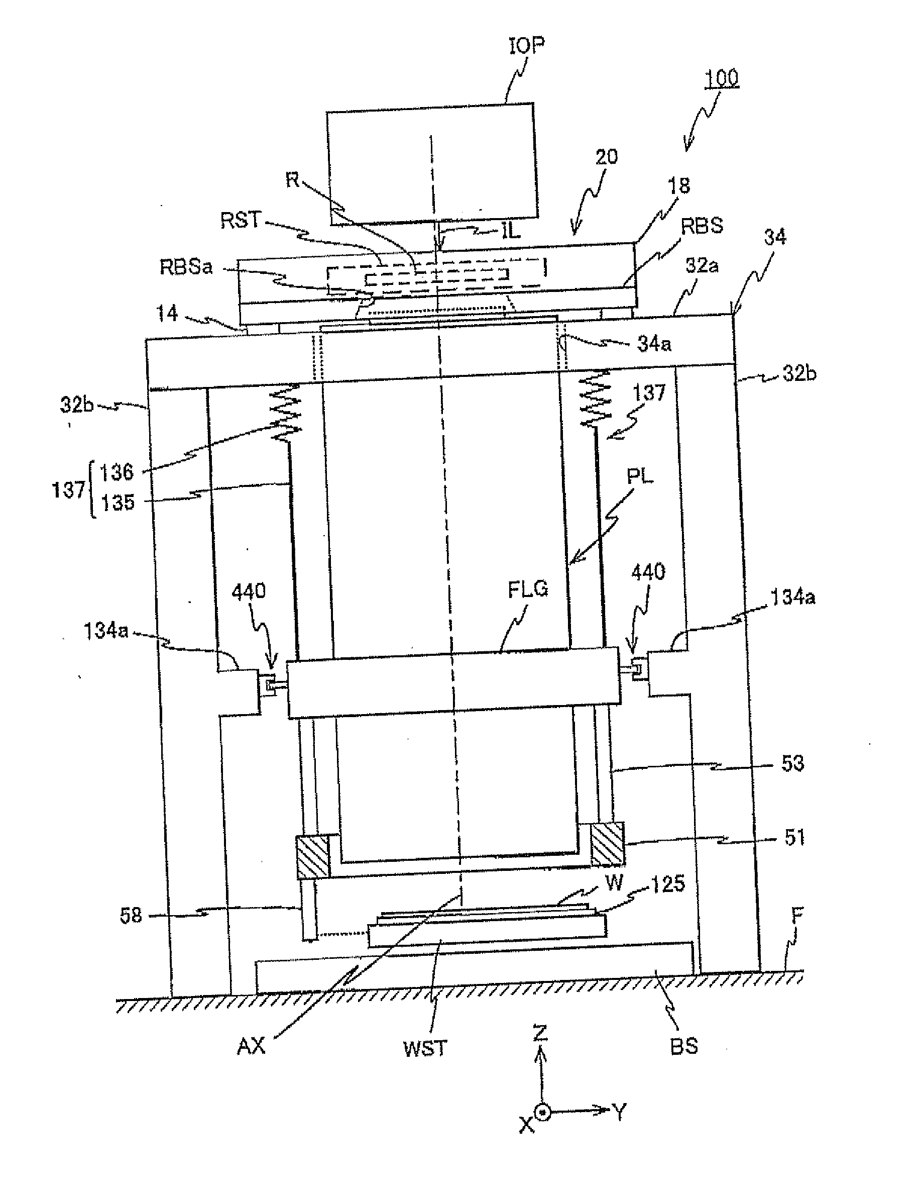
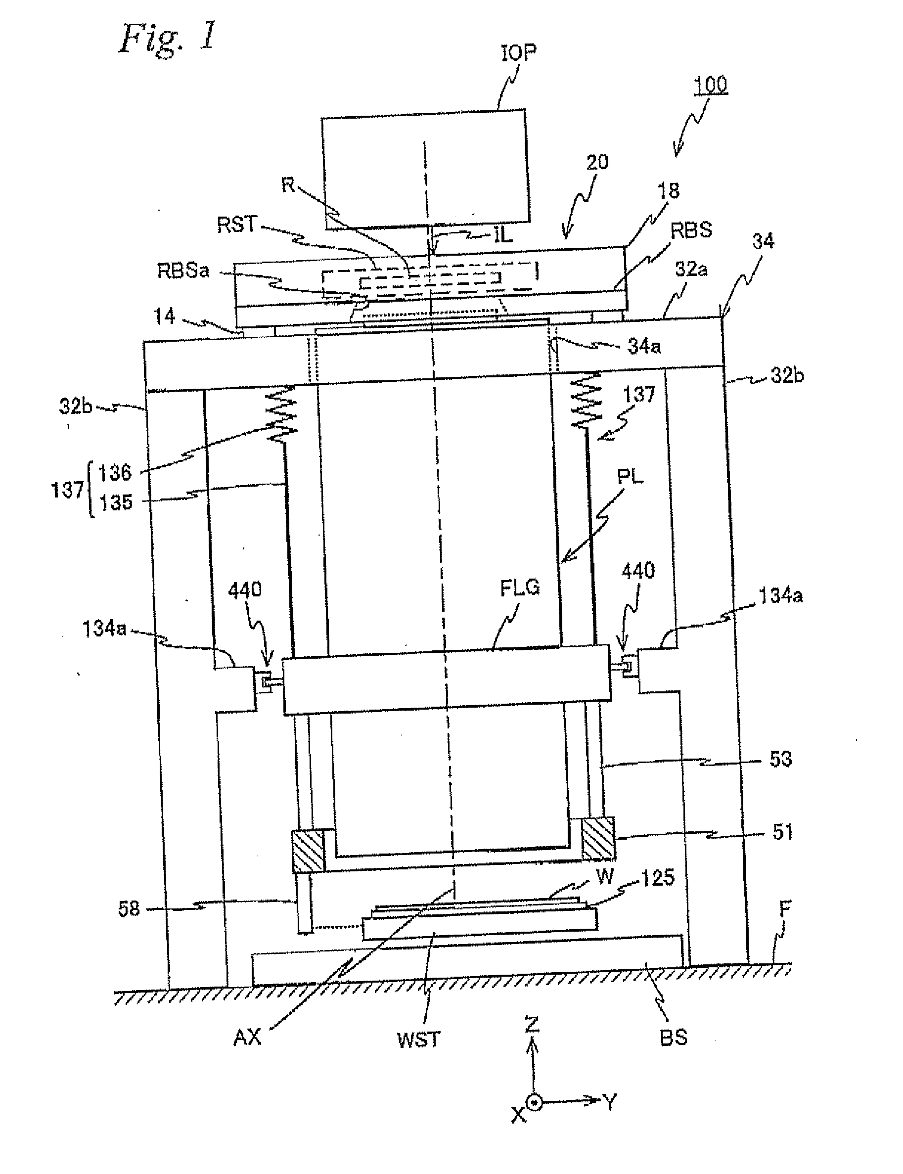
[0050]A first embodiment will be described below, with reference to FIGS. 1 to 6.

[0051]FIG. 1 schematically shows a configuration of an exposure apparatus 100 in the first embodiment. Exposure apparatus 100 is a projection exposure apparatus by the step-and-scan method, or a so-called scanning stepper (also called a scanner). As it will be described later, a projection optical system PL is arranged in the embodiment, and in the description below, a direction parallel to an optical axis AX of projection optical system PL will be described as the Z-axis direction, a direction within a plane orthogonal to the Z-axis direction in which a reticle and a wafer are relatively scanned will be described as the Y-axis direction, a direction orthogonal to the Z-axis and the Y-axis will be described as the X-axis direction, and rotational (inclination) directions around the X-axis, the Y-axis, and the Z-axis will be described as θx, θy, and θz directions, respectively.

[0052]Exp...

second embodiment

A Second Embodiment

[0137]Next, a second embodiment of the present invention will be described, with reference to FIGS. 7 to 12. Here, the same reference numerals will be used for the same or similar sections as in the first embodiment previously described, and a detailed description thereabout will be simplified or omitted.

[0138]FIG. 7 shows a block diagram showing an input / output relation of main controller 50, which centrally configures a control system of the exposure apparatus of the second embodiment. As is obvious when comparing FIGS. 6 and 7, in the exposure apparatus of the second embodiment, components similar to the first embodiment previously described are connected to main controller 50, and further, an auxiliary encoder system 87, a temperature controller 280, a drive section 46, and an X-ray ionizer 42 are connected. The description below includes these auxiliary encoder system 87, temperature controller 280, drive section 46, X-ray ionizer 42, and the embodiment will ...

third embodiment

A Third Embodiment

[0182]Next, a third embodiment will be described, with reference to FIGS. 13 to 15C. Here, the same reference numerals will be used for the same or similar sections as in the first embodiment previously described, and a detailed description thereabout will be simplified or omitted.

[0183]FIG. 13 shows a block diagram showing an input / output relation of main controller 50, which centrally configures a control system of the exposure apparatus of the third embodiment. As is obvious when comparing FIGS. 13 and 6, in the exposure apparatus of the third embodiment, components similar to the first embodiment previously described are connected to main controller 50, and further, a reticle AF sensor 130, and an auxiliary encoder system 170 are connected. In the description below, these reticle AF sensor 130 and auxiliary encoder system 170 are included, and the embodiment will be described focusing mainly on the difference with the first embodiment.

[0184]FIGS. 14A and 14B sh...


PUM


Abstract

One pair each of a Y linear motor (a total of four) on the +X side and the −X side that drive a reticle stage include one pair each of a stator section (a total of four) and three each of a mover section (a total of six) on the +X side and the −X side. In this case, the three each of the mover sections on the +X side and the −X side configure one each of a mover. The mover section located in the center in the Z-axis direction of each of the movers is used in common by each pair of the Y linear motors. Therefore, the weight of the mover section (reticle stage) of the reticle stage device is reduced, which allows a higher acceleration. Further, the mover section located in the center in the Z-axis direction of each of the movers coincides with a neutral plane of the reticle stage.

Description

CROSS-REFERENCE TO RELATED APPLICATIONS[0001]This non-provisional application claims the benefit of Provisional Application No. 61 / 272,075 filed Aug. 13, 2009, Provisional Application No. 61 / 272,094 filed Aug. 14, 2009, Provisional Application No. 61 / 272,096 filed Aug. 14, 2009 and Provisional Application No. 61 / 272,097 filed Aug. 14, 2009, the disclosures of which are hereby incorporated herein by reference in its entirety.BACKGROUND OF THE INVENTION[0002]1. Field of the Invention[0003]The present invention relates to movable body apparatuses, exposure apparatus, exposure methods, and device manufacturing methods, and more particularly, to a movable body apparatus including a movable body which holds an object and is movable in a direction parallel to a first axis in a two-dimensional plane, an exposure apparatus which is equipped with the movable body apparatus and is used in a lithography process to produce electronic devices (microdevices) such as a semiconductor device, a liqui...

Claims


Application Information

Patent Timeline
IPC IPC(8): G03B27/54G03B27/60G05G11/00
CPCG03F7/707G03F7/70725G03F7/70758Y10T74/20354G03F7/70858G03F7/70866G03F7/70941G03F7/70775G03F7/70133G03F7/70716G03F7/70933
Inventor SHIBAZAKI, YUICHI
Owner NIKON CORP
Why Eureka
Try Eureka