Electrical motor activation method having load torque adaptation

a technology of electric motors and torque adaptation, which is applied in the direction of motor/generator/converter stoppers, dynamo-electric converter control, instruments, etc., can solve the problem of constant load torque during a motor revolution, and achieve the effect of reducing the ripple of fluctuation of load in the motor rotation speed

Inactive Publication Date: 2011-02-10
CONTINENTAL TEVES AG & CO OHG
View PDF19 Cites 12 Cited by
  • Summary
  • Abstract
  • Description
  • Claims
  • Application Information

AI Technical Summary

Benefits of technology

[0005]An object of the present invention is to specify a motor drive method, such as a DC motor drive method, which provides a load-adapted motor current in a simple manner, so that, for example, an audible ripple of fluctuations in load in the motor rotation speed is reduced.

Problems solved by technology

However, the load torque during a revolution of the motor is not constant since the motor is connected to an angle-dependent load via the motor shaft.

Method used


Image

  • Electrical motor activation method having load torque adaptation
  • Electrical motor activation method having load torque adaptation
  • Electrical motor activation method having load torque adaptation

Examples


Embodiment Construction

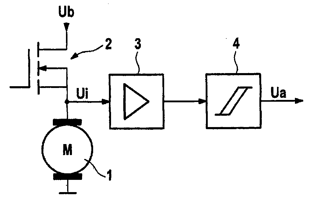
[0033]As illustrated in FIG. 1, motor 1 is driven in a pulsed manner by PWM driving of an electronic brake system. To this end, FET 2 is connected as a high-side switch between the poles of a DC voltage supply means and motor 1. The voltage Ui is tapped off at the motor connection of the motor 1 which faces the FET 2, said voltage, on account of the commutator of the motor, having a ripple which is dependent on the rotation speed. Voltage Ui is fed to an operational amplifier 3. The signal amplified by the operational amplifier 3 is converted into a rectangular digital signal by a Schmitt trigger 4.

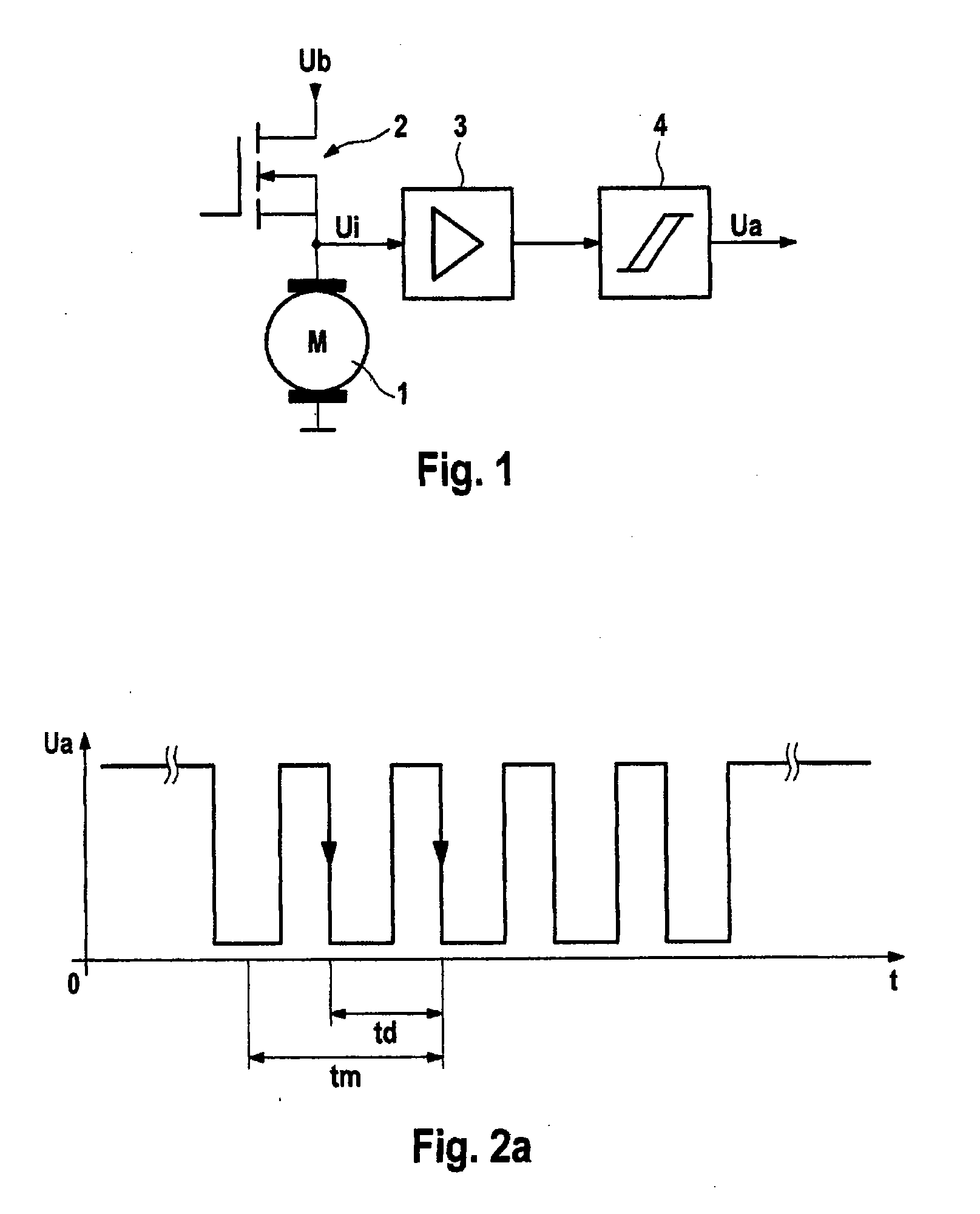
[0034]The diagram in FIG. 2a) shows the signal produced at the output of the Schmitt trigger 4. The signal has a rectangular profile and alternates between 0 and 5 V. The spacings of the flanks td vary as a function of the angular velocity of the motor shaft.

[0035]The brushed motor 1, from which the pulse signal in FIG. 2b) originates, is connected to the pump of the hydraulic system of a...


PUM


Abstract

An electrical motor activation method for an electric motor including a rotor, connected to a motor shaft, and a stator having brushes. The stator comprises multiple commutator laminations for the commutation of windings disposed on the rotor and is activated by a pulsed or linearly controllable power source. The motor shaft is connected to a radially driven load, in particular a pump, which has a nonlinear torque curve via a motor revolution. A waviness signal is obtained from a voltage potential applied to the motor and/or from the motor current and rotor position information is obtained from the curve of said waviness signal.

Description

CROSS REFERENCE TO RELATED APPLICATIONS[0001]This application is the U.S. national phase application of PCT International Phase Application No. PCT / EP2009 / 052718, filed Mar. 9, 2009, which claims priority to German Patent application No. 102008018818.2, filed Apr. 15, 2008, the contents of such application being incorporated by reference herein.FIELD OF THE INVENTION[0002]The invention relates to an electrical motor drive method and to the use of said method.BACKGROUND OF THE INVENTION[0003]WO 01 / 95471 A1, which is incorporated herein by reference, describes a method for determining the rotary position of the drive shaft of a DC motor, in which method the current ripple (actual current ripple) is evaluated. To this end, a suitable reference current ripple is compared with the actual current ripple which is measured during operation of the motor.[0004]DE 42 32 130 A1, which is incorporated herein by reference, discloses a circuit arrangement with which, in an ABS brake control device...

Claims


Application Information

Patent Timeline
Patent Type & Authority Applications(United States)
IPC IPC(8): F04B35/04H02P7/29
CPCB60T8/4059H02P7/28H02P7/0094
Inventor BARTHEL, DIETERHEISE, ANDREASHARTMANN, RALFBITSCH, CHRISTIANSCHMITZ, DANIELRICHTER, ANDREAS
Owner CONTINENTAL TEVES AG & CO OHG
Why Eureka
Try Eureka