
Scanning Near Field Thermoelastic Acoustic Holography (SNFTAH)

Inactive Publication Date: 2011-02-17
NORTHWESTERN UNIV
View PDF49 Cites 19 Cited by
  • Summary
  • Abstract
  • Description
  • Claims
  • Application Information

AI Technical Summary

Benefits of technology

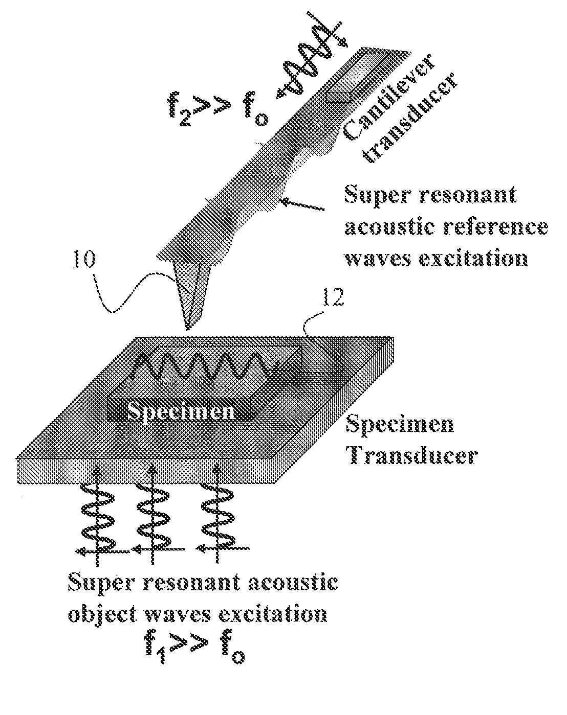
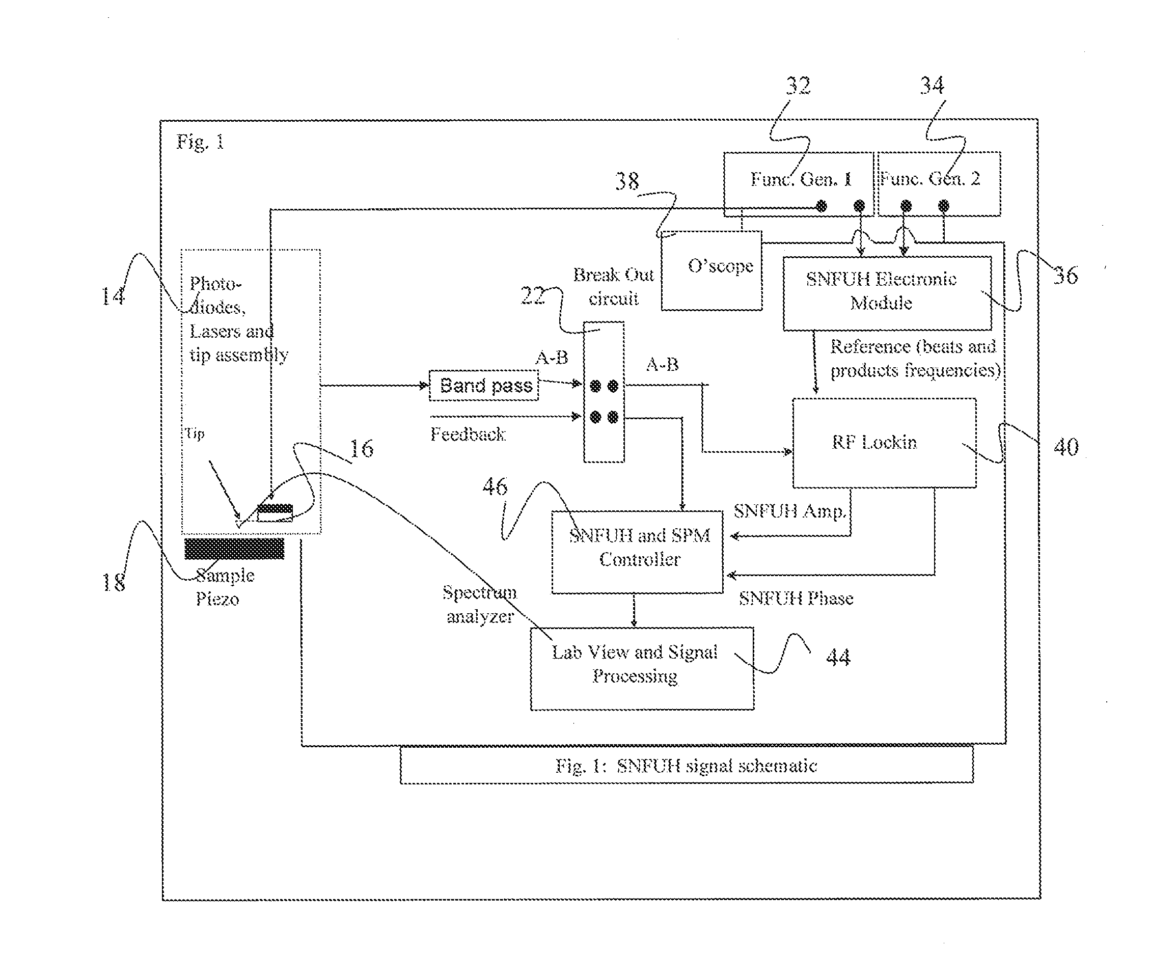
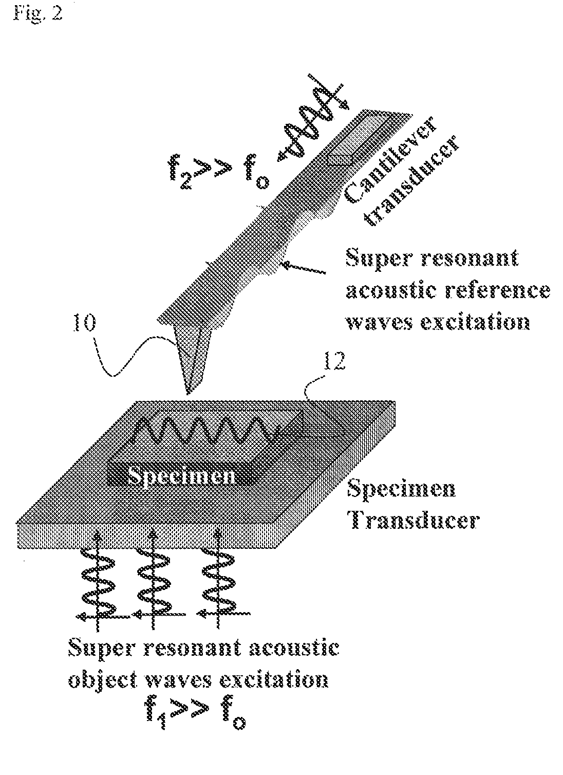
[0007]The present invention relates to a high spatial resolution phase-sensitive technique, which employs a scanning near field ultrasonic holography methodology for imaging buried or other subsurface structures or variation in the specimen. Scanning near field ultrasound holography (SNFUH) uses a near-field approach to measure time-resolved variations in ultrasonic oscillations at a sample surface. As such, it overcomes the spatial resolution limitations of conventional phase-resolved acoustic microscopy (i.e. holography) by eliminating the need for far-field acoustic lenses.
[0008]The fundamental static and dynamic nanomechanical imaging modes for the instrument of the present invention are based on nanoscale viscoelastic surface and subsurface (e.g., buried nanostructure) imaging using two-frequency ultrasonic holography. The scanning near-field ultrasonic technique of the present invention vibrates both the cantilevered tip and the sample at ultrasonic / microwave frequencies. The contact, soft-contact and near-contact modes of tip-sample interaction enable the extraction of the surface acoustic waves signal between the two ultrasonic vibrations.
[0011]Some embodiments according to the present invention provide that laser beam radiation is focused on a sample surface. As the laser beam radiation is absorbed by the sample surface, thermally induced expansion of the sample occurs which generates thermo acoustic waves through thermal waves. The carrier wave can be modulated with a very low frequency modulated waveform (e.g., a frequency of approximately 20 KHz to approximately 200 KHz). The amplitude, for example, of the modulated waveform riding on the carrier may change depending on the defects close to the sample surface or surface mechanical variation. A sharp SPM cantilever may be used to monitor the modulated surface acoustic wave to identify buried defects and / or to sample surface nanomechanical properties with very high spatial resolution. The amplitude signal, for example, may be fed into a lock-in amplifier and an output of the lock-in amplifier may be used to generate amplitude scanning near field thermoelastic acoustic holography (SNFTAH) images. Acoustic transducers and coupling solvents are not employed in some ultrasound holography methods according to some embodiments of the present invention. The frequency of the laser beam can be easily tuned from approximately a megahertz to approximately a gigahertz to attain diffraction limit free images with very high spatial resolution.

Problems solved by technology

Further, the acoustic microscope has two other major roadblocks in getting high resolution: (1) impedance mismatches and coupling fluid attenuation that is proportional to f2.
The drawback of ultrasonic microscopy is that it measures only the amplitude due to ultrasonically induced cantilever vibrations.
Moreover, where the sample is particularly thick and has a very irregular surface or high ultrasonic attenuation, only low surface vibration amplitude may be generated.
In such circumstances the amplitude of vibration may be below the sensitivity threshold of the microscope in which case measurement is impossible.
Moreover, none of the above mentioned techniques measures with high resolution the acoustic phase, which is very sensitive to subsurface elastic imaging and deep defects identification which are lying underneath the surface, without doing any cross sectioning of the samples.
Additionally, non-linear tip sample interaction may not provide results for soft materials.

Method used


Image

  • Scanning Near Field Thermoelastic Acoustic Holography (SNFTAH)
  • Scanning Near Field Thermoelastic Acoustic Holography (SNFTAH)
  • Scanning Near Field Thermoelastic Acoustic Holography (SNFTAH)

Examples


Embodiment Construction

[0036]Certain embodiments of the present invention are directed to a nondestructive, high resolution, sub-surface nanomechanical imaging system. The system is capable of directly and quantitatively imaging the elastic (static) and viscoelastic (dynamic) response of a variety of nanoscale materials and device structures with spatial resolution of a few nanometers depending on the ultrasonic frequencies. For viscoelastic high resolution sub-surface nanomechanical imaging the target maximum probe frequency is around 5-10 GHz, for example. In an embodiment, the maximum relative phase resolution at this frequency is estimated to be 0.001° leading to a viscoelastic time resolution of less than <1 ps. The instrument of certain embodiments of the present invention operates in a manner similar to commercially available scanning probe microscopes (SPMs) in that quantitative, digital, rastered, nanometer-scale images are obtained of the sample elastic modulus, and sample viscoelastic response ...


PUM


Abstract

A system and method for analyzing a sample is described. The system may include, for example, a light source and a scanning probe microscope probe. The light source may generate a coherent laser beam that is modulated by a waveform of a lower frequency. The modulated laser beam is absorbed by the sample causing thermally induced expansion and resulting in an excitation of acoustic waves. The probe is locally deployed near the sample and detects, in real time, perturbations in the excited acoustic waves to detect surface and buried structures of the sample.

Description

CROSS-REFERENCE TO RELATED APPLICATIONS[0001]This application is a continuation-in-part of U.S. patent application Ser. No. 12 / 886,929, filed Sep. 21, 2010, which is a continuation of U.S. patent application Ser. No. 12 / 244,406, filed Oct. 2, 2008, now U.S. Pat. No. 7,798,001, which is a continuation of U.S. patent application Ser. No. 11 / 244,747, filed Oct. 6, 2005, now U.S. Pat. No. 7,448,269, which is a continuation-in-part of U.S. patent application Ser. No. 10 / 913,086, filed Aug. 6, 2004, which claims benefit from and priority to U.S. Provisional Application No. 60 / 494,532, filed Aug. 12, 2003. The above-identified applications are hereby incorporated herein by reference in their entirety.STATEMENT REGARDING FEDERALLY SPONSORED RESEARCH OR DEVELOPMENT[0002]This invention was made with government support under Grant Number DB1-0649916 / 001 awarded by the National Science Foundation. The government has certain rights in the invention.BACKGROUND OF THE INVENTION[0003]Known acoustic...

Claims


Application Information

Patent Timeline
IPC IPC(8): G01N29/04
CPCG01N29/0663G01N29/0681G01N29/2418G01N29/265G03H3/00G01N2291/0232G01N2291/02827G01N2291/0427G01N2291/0231G01Q60/32
Inventor SHEKHAWAT, GAJENDRA S.DRAVID, VINAYAK P.
Owner NORTHWESTERN UNIV
Learn More