Method for designing a diffraction grating structure and a diffraction grating structure

a diffraction grating and design method technology, applied in the field of diffraction grating structure and diffraction grating structure design, can solve the problems of not being able to find a universally applicable solution for controlling the wavelength response of a diffraction grating in the prior art, and achieve the effect of accurate final performance of the realized grating

Inactive Publication Date: 2011-02-17
NANOCOMP
View PDF4 Cites 51 Cited by
  • Summary
  • Abstract
  • Description
  • Claims
  • Application Information

AI Technical Summary

Benefits of technology

[0016]In one preferred embodiment of the present invention, when determining the desired diffraction efficiencies ηd to be substantially constant in a wavelength range from λ1 to λ2, the pillars and grooves are dimensioned so as to produce the differences in the calculated phase shifts Φ between adjacent pillars substantially constant in that wavelength range. The calculated phase shift of one pillar of height h having effective index neff is Φ=neffh2π / λ. The phase difference between two pillars of equal heights is then ΔΦ=(Δneff)h2π / λ. Thus, the phase shift ΔΦ can be set to be constant by choosing the effective indices so that their difference Δneff is proportional to wavelength λ. When seeking substantially constant diffraction efficiencies, the minimum value of the difference in the calculated phase shifts for any two adjacent pillars is preferably at least 80%, more preferably at least 90% of the maximum value. The substantially flat wavelength response achievable with this embodiment of the present invention is very advantageous in many applications.
[0017]In another preferred embodiment of the present invention, the desired diffraction efficiencies ηd are determined to have a non-constant wavelength response, and the pillars and grooves are dimensioned so as to produce said correspondence between the differences in the calculated phase shifts Φ of adjacent pillars and the phase profile Φr required by the desired diffraction efficiencies at several wavelengths λi. When the desired diffraction efficiencies ηd of the diffraction orders depend on the wavelength, there is a specific phase profile Φr required by those diffraction efficiencies for each wavelength λi, respectively. By said producing said correspondence at several wavelengths, the grating structure is made carry out the desired non-constant diffraction performance. The more wavelengths are treated, the more accurately the final performance of the realized grating follows the desired diffraction efficiencies. A very advantageous feature of this embodiment of the present invention is that principally any wavelength response of the diffraction performance can be achieved.

Problems solved by technology

Despite the continuous development both in designing and manufacturing of effective grating structures, one serious problem still exists.
However, the general situation is that no universally applicable solution for controlling the wavelength response of a diffraction grating is known in the prior art.

Method used


Image

  • Method for designing a diffraction grating structure and a diffraction grating structure
  • Method for designing a diffraction grating structure and a diffraction grating structure
  • Method for designing a diffraction grating structure and a diffraction grating structure

Examples


Embodiment Construction

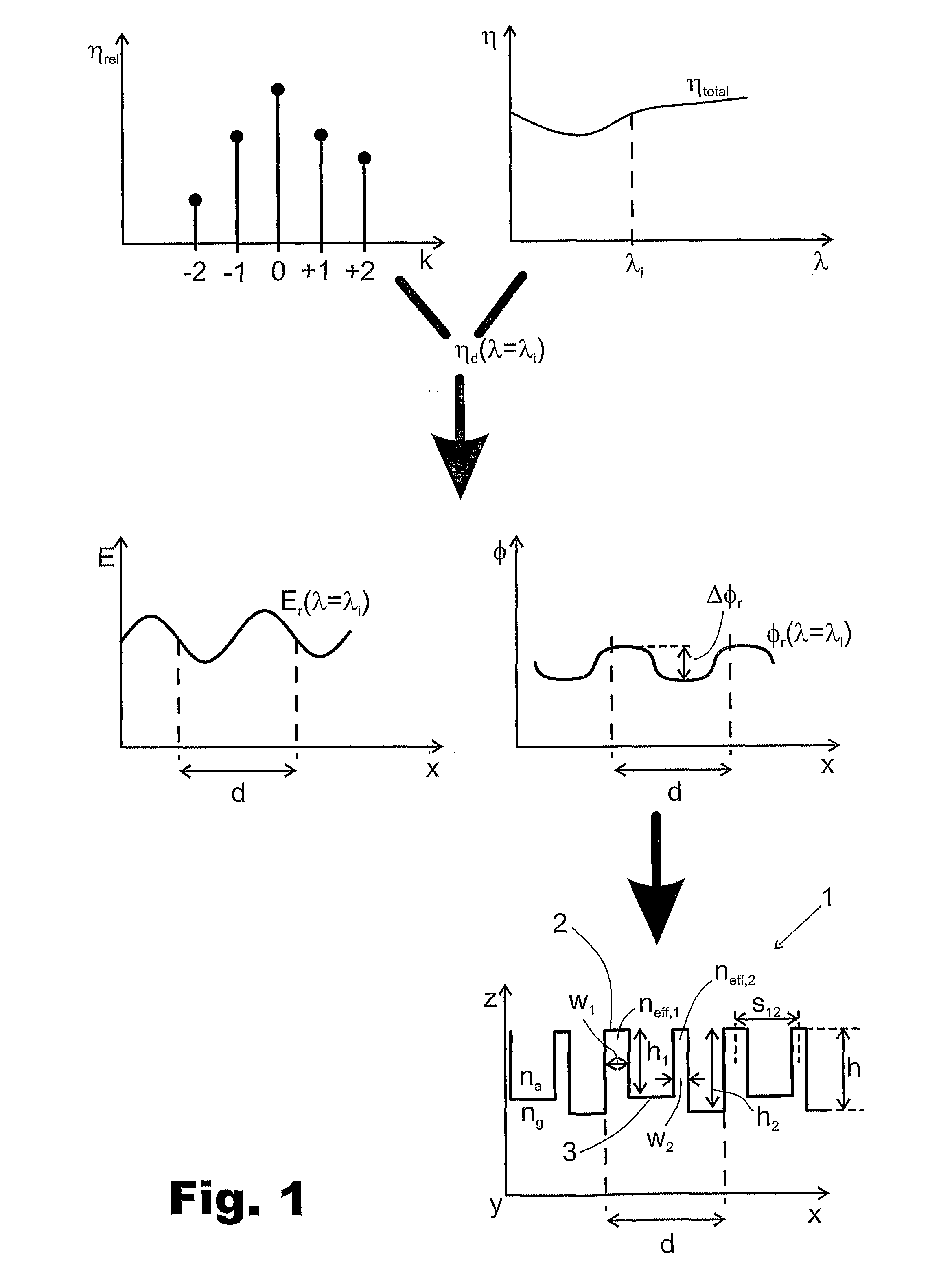
[0031]The designing process illustrated by graphs of FIG. 1 starts by determination of the desired diffraction efficiencies of different diffraction orders k and the wavelength dependence of the diffraction performance. Desired diffraction efficiencies can be determined as relative proportions ηrel of the total diffraction efficiency ηtotal i.e. the sum diffraction efficiencies of all diffraction orders excluding the zeroth one, as shown in FIG. 1, or by absolute efficiencies e.g. by means of square of transmission. In the procedure of FIG. 1, it is approximated that the mutual proportions of the diffraction orders other than the zeroth one remain constant and the wavelength response is treated as the wavelength response of the total diffraction efficiency ηtotal. Whatever is the way of determining the desired diffraction efficiencies, there is principally a specific set of desired diffraction efficiencies ηd of different diffraction orders for each wavelength λi. Thus, one can then...


PUM


Abstract

According to the present invention, the method for designing a diffraction grating structure (1), the grating period (d) of the structure comprising at least two grating lines each consisting of a pair of adjacent pillars (2) and grooves (3), comprises the steps of—determining desired diffraction efficiencies ηd of the diffraction orders, and—dimensioning the pillars (2) and grooves (3) so that when calculating for each pillar, on the basis of the effective refractive index neff for the fundamental wave mode propagating along that pillar, the phase shift Φ experienced by light propagated through the grating structure, the differences in the calculated phase shifts between adjacent pillars corresponds to the phase profile Φr required by the desired diffraction efficiencies.

Description

FIELD OF THE INVENTION[0001]The present invention relates to the designing procedure of diffraction grating structures and diffraction grating structures, the focus being on the wavelength dependence of the grating performance.BACKGROUND OF THE INVENTION[0002]Diffraction gratings are important components in micro-optics enabling effective light manipulation in a great variety of applications. Some typical applications include e.g. coupling light into and out from a waveguide or light guide, transforming a light beam into a wider beam or several sub-beams, and shaping an initially non-optimal geometry of a laser beam.[0003]Despite the continuous development both in designing and manufacturing of effective grating structures, one serious problem still exists. In surface relief and volume gratings, the light propagating through the grating structure experiences a phase shift proportional to ngh / λ, wherein ng is the refractive index of the grating material, h is the grating structure th...

Claims


Application Information

Patent Timeline
Patent Type & Authority Applications(United States)
IPC IPC(8): G02B5/18G06F17/50
CPCG02B5/1809
Inventor VALLIUS, TUOMASPIETARINEN, JUHALAAKKONEN, PASI
Owner NANOCOMP
Why Eureka
Try Eureka