Refrigeration apparatus

a technology of refrigerant and exchanger, which is applied in the direction of refrigerating machines, lighting and heating apparatus, compression machines with reversible cycles, etc., can solve the problems of high heat radiation loss of exchangers, difficult to achieve high operating efficiency, and temperature difference between refrigerants, etc., and achieves greater injection ratio

Active Publication Date: 2011-03-03
DAIKIN IND LTD +1
View PDF10 Cites 26 Cited by
  • Summary
  • Abstract
  • Description
  • Claims
  • Application Information

AI Technical Summary

Benefits of technology

[0030]In view of this, the target value of the degree of superheating during the heating operation is set in this refrigeration apparatus to the same value as the target value of the degree of superheating during the cooling operation, whereby the refrigerant drawn into the second-stage compression element during the heating operation is cooled by intermediate pressure injection during the heating operation to the same degree of superheating as that of the cooling operation for cooling the refrigerant by the intermediate heat exchanger and by intermediate pressure injection, and the injection ratio is greater during the heating operation than during the cooling operation by an amount equivalent to the cooling effect by the intermediate heat exchanger. Thereby, in this refrigeration apparatus, in cases in which the target value of the degree of superheating during the cooling operation is set near a value corresponding to the optimum injection ratio at which the coefficient of performance during the cooling operation reaches a maximum, the injection ratio during the heating operation as well approaches the optimum injection ratio at which the coefficient of performance during the heating operation reaches a maximum, and intermediate pressure injection can be performed at the optimum injection ratio at which the coefficient of performance reaches a maximum during both the cooling operation and the heating operation.

Problems solved by technology

As a result, since the refrigerant discharged from the second-stage compression element of the compressor has a high temperature, there is a large difference in temperature between the refrigerant and the water or air as a cooling source in the outdoor heat exchanger functioning as a refrigerant radiator, and the outdoor heat exchanger has much heat radiation loss, which poses a problem in making it difficult to achieve a high operating efficiency.
However, during the heating operation, if the intermediate heat exchanger is not provided, the heat that should be useable in the usage-side heat exchanger is radiated to the exterior from the intermediate heat exchanger, and operating efficiency therefore decreases.

Method used


Image

  • Refrigeration apparatus
  • Refrigeration apparatus
  • Refrigeration apparatus

Examples


modification 1

(3) Modification 1

[0097]In the embodiment described above, in the air-conditioning apparatus 1 configured to be capable of switching between the air-cooling operation and the air-warming operation via the switching mechanism 3, the first second-stage injection tube 18c is provided for performing intermediate pressure injection through the receiver 18 as a gas-liquid separator, and intermediate pressure injection is performed by the receiver 18 as a gas-liquid separator, but instead of intermediate pressure injection by the receiver 18, another possible option is to provide a third second-stage injection tube 19 and an economizer heat exchanger 20 and to perform intermediate pressure injection through the economizer heat exchanger 20.

[0098]For example, as shown in FIG. 9, a refrigerant circuit 110 can be used which is provided with the third second-stage injection tube 19 and the economizer heat exchanger 20 instead of the first second-stage injection tube 18c in the embodiment descr...

modification 2

(4) Modification 2

[0115]In the refrigerant circuits 10 and 110 (FIGS. 1 and 9) in the embodiment and its modification described above, to reduce heat radiation loss in the heat source-side heat exchanger 4 during the air-cooling operation, the intermediate heat exchanger 7 which functions as a cooler of refrigerant discharged from the first-stage compression element 2c and drawn into the second-stage compression element 2d is provided to the intermediate refrigerant tube 8 for drawing refrigerant discharged from the first-stage compression element 2c into the second-stage compression element 2d, and to suppress heat radiation to the exterior and enable the heat to be used in the usage-side heat exchanger 6 functioning as a radiator of refrigerant during the air-warming operation, the intermediate heat exchanger bypass tube 9 for bypassing the intermediate heat exchanger 7 is provided, creating a state in which the intermediate heat exchanger 7 is not used during the air-warming oper...

modification 3

(5) Modification 3

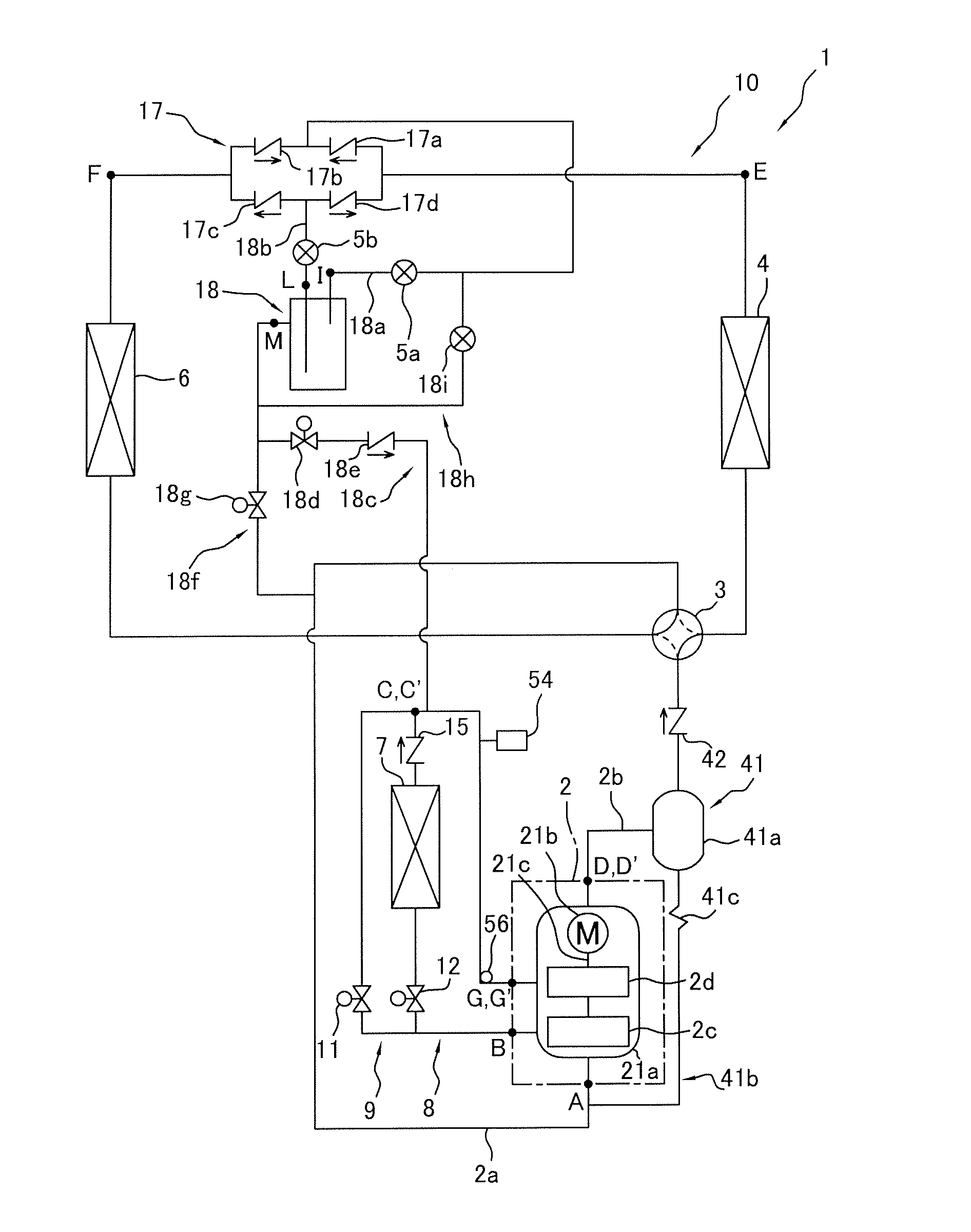
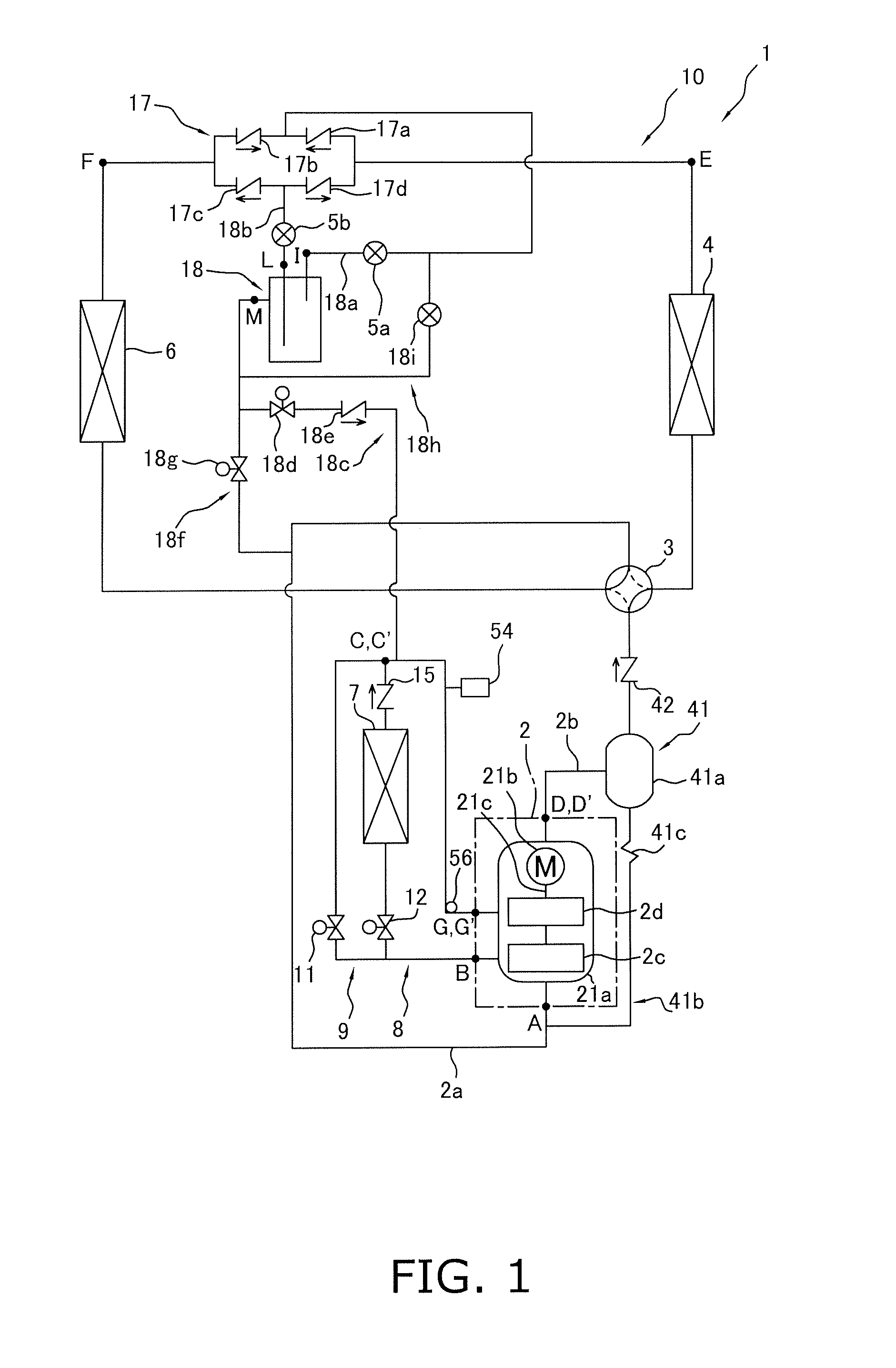
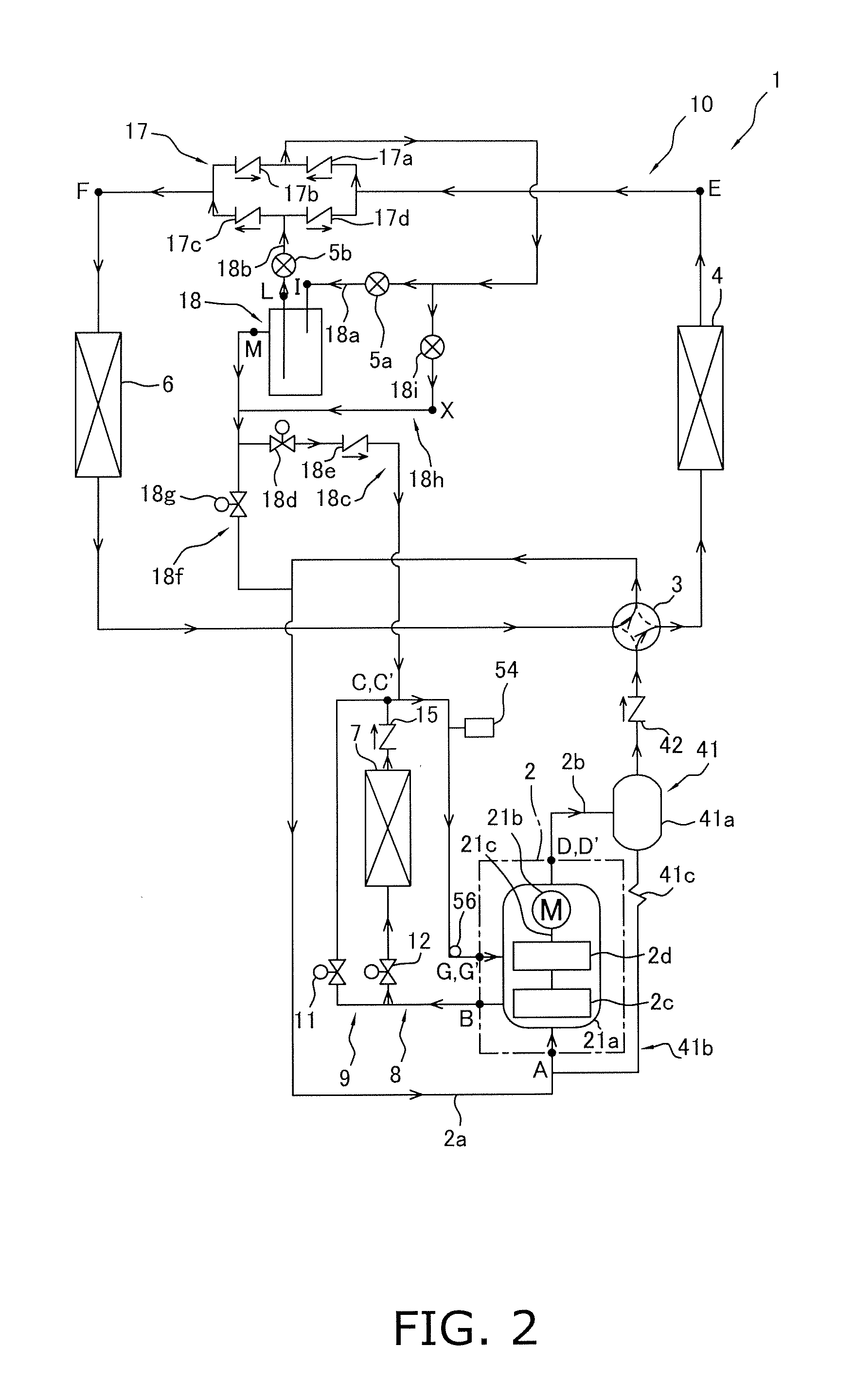
[0128]In the refrigerant circuit 10 (see FIG. 1) in the embodiment described above, wherein intermediate pressure injection is performed by the receiver 18 as a gas-liquid separator and liquid injection is performed by the liquid injection tube 18h as a second second-stage injection tube, another possibility is to configure a refrigerant circuit to have a plurality of usage-side heat exchangers 6 connected in parallel to each other (see FIG. 21), and to provide usage-side expansion mechanisms 5c (see FIG. 21) so as to correspond to each of the usage-side heat exchangers 6 in order to control the flow rates of the refrigerant flowing through each of the usage-side heat exchangers 6 and achieve the refrigeration loads required in each of the usage-side heat exchangers 6. In this case, during the air-warming operation, the flow rates of the refrigerant passing through each of the usage-side heat exchangers 6 are determined for the most part by the opening degrees of t...


PUM


Abstract

A refrigeration apparatus includes a multi-stage compression mechanism, heat source-side and usage side heat exchangers each operable as a radiator/evaporator, a switching mechanism switchable between cooling and heating operation states, a second-stage injection tube, an intermediate heat exchanger and an intermediate heat exchanger bypass tube. The intermediate heat exchanger bypass tube ensures that refrigerant discharged from the first-stage compression element and drawn into the second-stage compression element is not cooled by the intermediate heat exchanger during a heating operation. Injection rate optimization controls a flow rate of refrigerant returned to the second-stage compression element through the second-stage injection tube so that an injection ratio is greater during the heating operation than during a cooling operation. The injection ratio is a ratio of flow rate of the refrigerant returned to the second-stage compression element through the second-stage injection tube relative to flow rate of the refrigerant discharged from the compression mechanism.

Description

TECHNICAL FIELD[0001]The present invention relates to a refrigeration apparatus, and particularly relates to a refrigeration apparatus for performing a multi-stage compression-type refrigeration cycle having a refrigerant circuit which can switch between a cooling operation and a heating operation and which is capable of intermediate pressure injection.BACKGROUND ART[0002]As one conventional example of a refrigeration apparatus for performing a multi-stage compression-type refrigeration cycle having a refrigerant circuit which can switch between a cooling operation and a heating operation and which is capable of intermediate pressure injection, Patent Literature 1 (Japanese Laid-open Patent Application No. 2007-232263) discloses an air-conditioning apparatus for performing a two-stage compression-type refrigeration cycle having a refrigerant circuit which can switch between an air-cooling operation and an air-warming operation and which is capable of intermediate pressure injection....

Claims


Application Information

Patent Timeline
Patent Type & Authority Applications(United States)
IPC IPC(8): F25B13/00F25B1/10F25B43/00F25B41/00
CPCF25B1/10F25B13/00F25B45/00F25B2400/23F25B2313/02741F25B2400/04F25B2400/072F25B2313/0272
Inventor FUJIMOTO, SHUJIYOSHIMI, ATSUSHI
Owner DAIKIN IND LTD
Why Eureka
Try Eureka