Controllable Lighting System

a controllable lighting and control panel technology, applied in the field of lighting, can solve the problems of inconvenient replacement of led modules, inconvenient installation, and inability to control the lighting system, etc., and achieve the effects of reducing the cost of installation

Inactive Publication Date: 2011-03-03
FIREFLY LED LIGHTING
View PDF24 Cites 65 Cited by
  • Summary
  • Abstract
  • Description
  • Claims
  • Application Information

AI Technical Summary

Problems solved by technology

The replacement of conventional incandescent light bulbs with one or more LEDs is desirable because incandescent bulbs are inefficient relative to LEDs in terms of energy efficiency, heat management, and longevity.
However, due to their unique shape, size, and power consumption requirements, they present manufacturing and assembly difficulties that were originally unanticipated by LED manufacturers, resulting in generally bulky and non-serviceable components.
Additionally, removal and replacement of LEDs in an LED module is often costly, cumbersome, impossible, and / or time consuming.
Despite the prevalence of their use, LEDs and LED modules have well known disadvantages and limitations.
Complexities of heat removal from LED packages and overall thermal management difficulties result in manufacturers de-rating the luminous output of lamps to minimize heat loading.
Some manufacturers attempt to solve the thermal management problem with complex and costly cast heat sink designs.
This approach greatly increases design and manufacturing cost and drives the lamp cost to a non-competitive price point.
Also, serious heat transfer or conduction problem arise when a plurality of densely packaged chips are used.
Currently known lighting systems have failed to assemble multiple LEDs in a compact fashion while maintaining the necessary heat transfer characteristics.
Also, LED lighting systems dissipate heat by a different heat transfer path than ordinary filament bulb systems; more specifically, these higher power LED lighting systems dissipate a substantial amount of heat via a cathode (negative terminal) leg or through a die attached to a thermal slug in a direct die mount device.
Consequently, the higher power LED systems tend to run at higher temperatures.
Higher operation temperatures degrade the performance of the higher power LED lighting systems.
Additionally, LED modules for use in a display or an illumination device have many LEDs, and most of the LEDs are driven at the same time, which results in a quick rise in temperature of the LED module.
Consequently light output quality from the LED module is degraded with illumination and shows undesirable color shift, flicker, and reduced intensity.
A substantial technical challenge to producing a reliable device based on LED light sources lies in packaging the light sources such that effective thermal management is realized.
Excessive operating temperature of the light sources often results in premature failure.
Both of these approaches have their drawbacks with respect to ease of replacements, cost, efficiency, or the like.
A major shortcoming of prior art heat sink design is that they are generally difficult to manufacture.
Such heat sinks require enormously high production cycle time and tooling costs to manufacturer which, of course, makes them cost ineffective.
The manufacturing techniques for heat sinks implemented in LED modules are die casting, die forging, precision sawing, electrical discharge machining, and numerically controlled machining In some prior art solutions, a method of manufacturing a pin-finned heat sink from an extrusion is limited by what is obtainable by an extrusion process.
A major shortcoming of such heat sinks is their high cost.
This cost is related directly to the labor required to individually arrange each fin on some sort of support or substrate and high production cycle time.
However, typical distribution characteristics of a typical LED means that a relatively large distance is generally be required for light mixing.
Existing lighting systems are limited in the sense that they have generally involved light sources coupled to a source of power via manually operated mechanical switches.
The result is lack of automation control and intelligent control of various lighting scenarios.
Furthermore, a network of lighting modules is highly inefficient in terms of intensity per unit of power consumed.
Additionally, such a network of lighting devices is unable to effectively and efficiently produce desired hue and color variations.
A significant problem with present lighting networks is that they require special wiring or cabling.
Another significant problem with present lighting network is that particular lighting applications require particular lighting types.

Method used


Image

  • Controllable Lighting System
  • Controllable Lighting System
  • Controllable Lighting System

Examples


Embodiment Construction

Incorporation by Reference

[0068]The following references are hereby incorporated by reference in their entirety as though fully and completely set forth herein:

[0069]U.S. Provisional Patent Application No. 61 / 275,401 titled “Lighting Device, Features, And Manufacturing Methods,” filed on Aug. 28, 2009.

Terms

[0070]The following is a glossary of terms used in the present application:

[0071]Memory Medium—Any of various types of memory devices or storage devices. The term “memory medium” is intended to include an installation medium, e.g., a CD-ROM, floppy disks 104, or tape device; a computer system memory or random access memory such as DRAM, DDR RAM, SRAM, EDO RAM, Rambus RAM, etc.; a non-volatile memory such as a Flash, magnetic media, e.g., a hard drive, or optical storage; registers, or other similar types of memory elements, etc. The memory medium may comprise other types of memory as well or combinations thereof. In addition, the memory medium may be located in a first computer in...


PUM

PropertyMeasurementUnit
separation distanceaaaaaaaaaa
temperatureaaaaaaaaaa
poweraaaaaaaaaa

Abstract

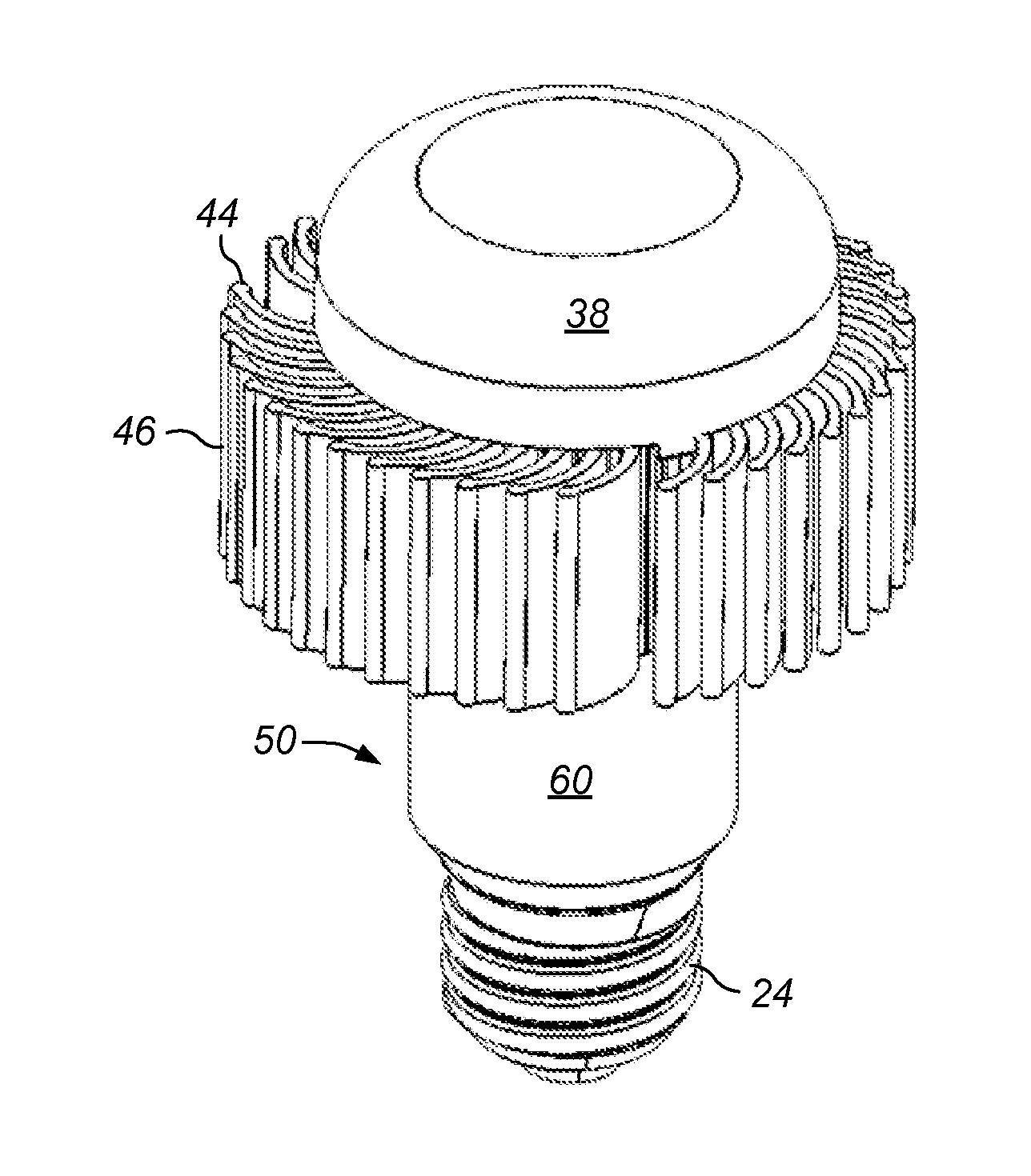
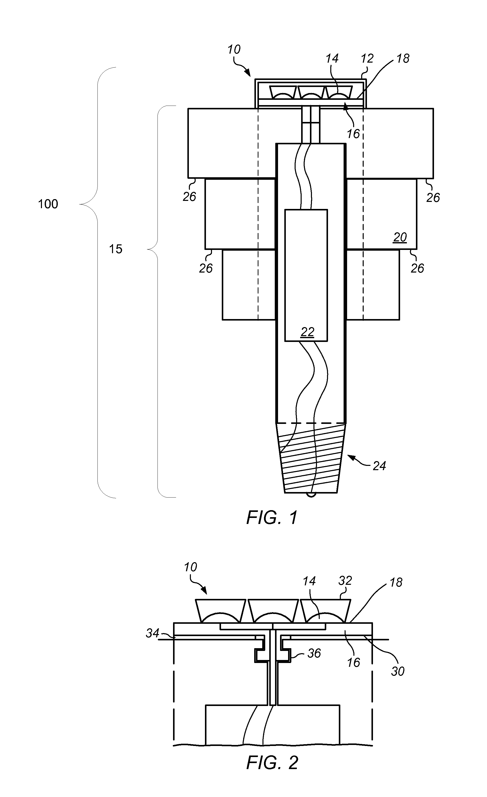
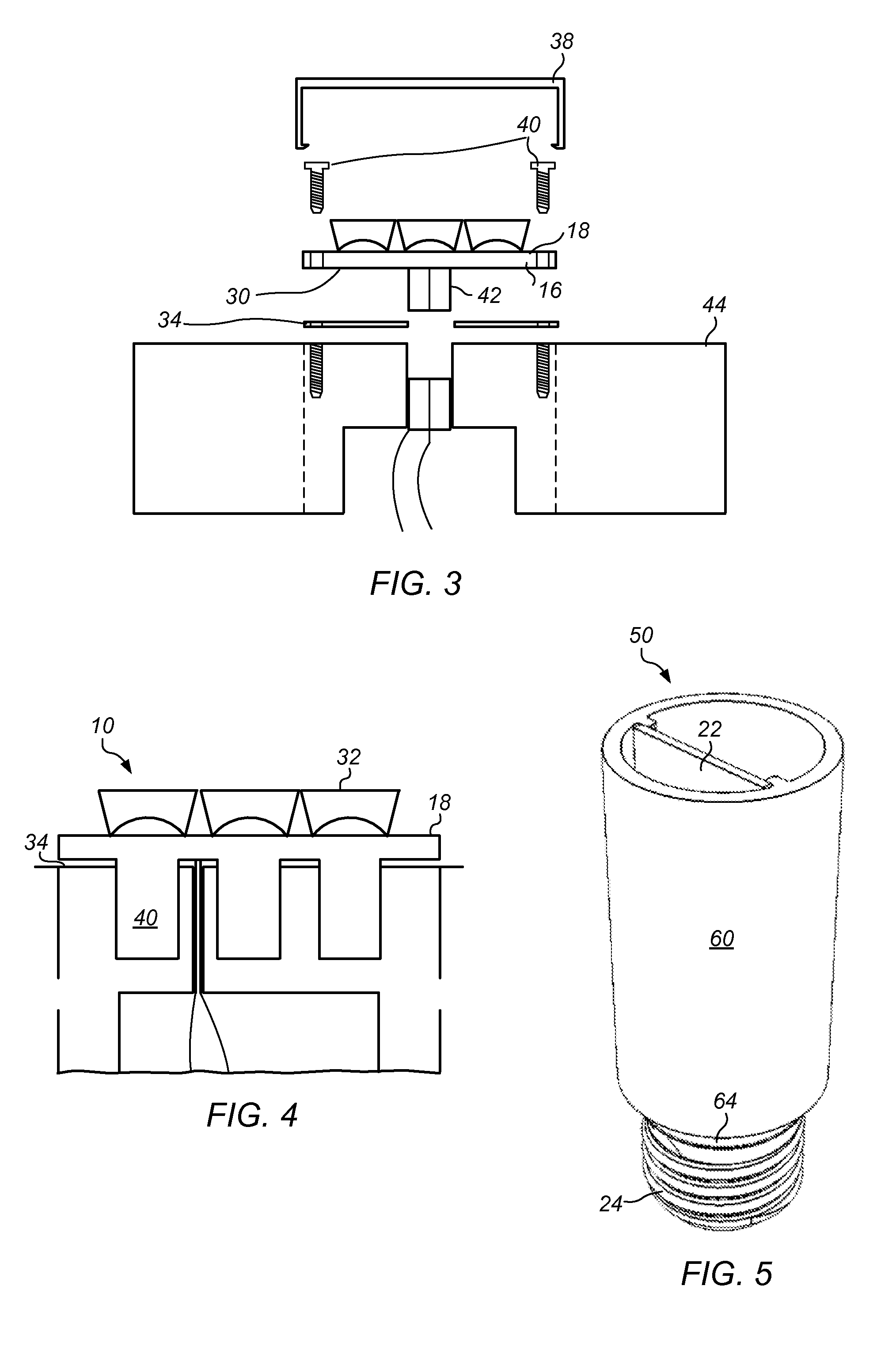
A lighting system is presented that includes a replaceable illumination module removably coupled to a base module. The replaceable illumination module includes one or more solid state lighting elements on a printed circuit board electrically and thermally connected to the base module. The base module may include a heat sink, where the heat sink is in thermal contact with the replaceable illumination module, and dissipates heat generated by the one or more solid state lighting elements during operation of the lighting system. The replaceable illumination module may also include one or more beam conditioning elements for generating a specified beam. The lighting system may be connected to an automated control network and may be automatically controlled thereby, or may be used to control some other system. The heat sink may be generated via a dynamically controllable extrusion die.

Description

PRIORITY DATA[0001]This application claims benefit of priority to U.S. Provisional Patent Application No. 61 / 275,401 titled “Lighting Device, Features, And Manufacturing Methods,” filed on Aug. 28, 2009, whose inventors were Stephen Barcik, Bill Kernion, and Brad Bailey which is hereby incorporated by reference in its entirety as though fully and completely set forth herein.FIELD OF THE INVENTION[0002]The present invention relates to lighting, and more particularly, to a solid state lighting replacement for lighting devices or systems and its operation.DESCRIPTION OF THE RELATED ART[0003]U.S. and international regulations call for phasing out existing lighting solutions, such as incandescent light bulbs, fluorescent lamps, and electrical ballasts. As a result, the light emitting diode (LED) and solid state lighting industry is growing rapidly. Industry and end users are calling for LEDs to be replacements for traditional lighting systems, such as those associated with traffic contro...

Claims


Application Information

Patent Timeline
Patent Type & Authority Applications(United States)
IPC IPC(8): H01J13/46H05B37/02H01J13/32B29C48/92
CPCF21K9/13F21V29/83F21V3/00F21V15/01F21V19/001F21V19/045F21V23/0442F21V29/02F21Y2101/02F21Y2105/00F21Y2111/004F21V23/0457F21V29/006F21V29/20F21V19/0055B29C47/92F21V29/673F21V29/713F21V29/74F21V29/75F21V29/81F21K9/135B29C48/92F21V19/04F21V29/54F21K9/23F21K9/232F21Y2107/20F21Y2115/10F21Y2115/15
Inventor BAILEY, JOEL BRADBARCIK, STEPHEN J.KERNION, WILLIAM J.
Owner FIREFLY LED LIGHTING
Why Eureka
Try Eureka