Uniform diffractive backlight

a backlight and diffractive technology, applied in the field of backlights, can solve the problems of introducing substantial non-uniformity, inefficiency of reflection and a second pass of light, and low efficiency of extraction, so as to improve the efficiency of light extraction and maintain the uniformity of extracted ligh

Inactive Publication Date: 2011-03-03
SHARP KK
View PDF7 Cites 8 Cited by
  • Summary
  • Abstract
  • Description
  • Claims
  • Application Information

AI Technical Summary

Benefits of technology

[0012]The present invention provides an apparatus and method for improving light extraction efficiency from a lightguide and maintaining uniformity of the extracted light on the simplest sub-wavelength structures: one and two dimensional rectangular and square gratings. The principles in accordance with the invention also can be applied to more complex gratings.
[0015]With the use of a sub-wavelength grating structure, it is possible to control many aspects of the light that is emitted from the lightguide. For example it is possible to control angular distribution, polarization etc. that would be very important for a transmissive spatial light modulator (SLM) based on polarization such as a liquid crystal display LCD. Control of angular distribution allows higher brightness without many additional components allowing more efficient, brighter and thinner displays. Many of these properties can be obtained by simple grating structures of varying types.
[0017]An apparatus and method in accordance with a preferred embodiment of the invention pertain to extraction features that have a high efficiency of extraction while maintaining the properties outlined above. In a preferred embodiment, a simple two level grating structure can be optimized for a particular extraction property, and can have an enhanced and controllable extraction by the superposition of a second grating cut into the “peaks” of the first grating. The second cutaway can have the same pitch as the first grating and can have a width that is less than the width of the “peak” of the first grating. This feature works by interference to enhance the extraction from a given area of feature.
[0018]The depth of the extraction feature can be changed with position, thereby allowing controllable extraction (meaning that the whole lightguide can be covered). This reduces moirè effects, improves uniformity and improves the overall efficiency of extraction by having greater coverage over the lightguide. This also allows the features to be constructed more simply in a nano-imrint mold instead of being patterned across the lightguide. The extraction structure may be on one or both sides of the lightguide.
[0019]In a second aspect of the invention a further improvement is provided that may be used with the preferred embodiment but also with a normal grating on its own. More particularly, the efficiency of extraction of light is higher for light rays at a smaller angle to the surface normal than others. In this case the lightguide can be designed with a series of stepped sloping features on the opposite side from the extraction features. This changes the angular distribution so that more rays at low angle to the normal are incident as they are “depleted” across the lightguide. This allows both more efficient extraction and improved uniformity. These features are not designed to extract light themselves, only to alter the angular distribution on the features.
[0021]According to one aspect of the invention, the extraction structure utilizes interference to enhance light extraction from a given area of feature.

Problems solved by technology

Reflection and a second pass of light are generally inefficient and introduce substantial non-uniformity.
Because of this, the efficiency of extraction is generally low, especially where the features are only refractive index gratings.
In addition, patterning the extraction means a substantial fraction of the lightguide surface (especially near the light sources) is not used for extraction reducing further the overall extraction efficiency.
This means it is often very difficult to get full efficient extraction using only diffractive features.
Although not reported, overall extraction efficiency is expected to be poor especially for small area backlights.
The efficiency of this design is limited by the period of the grating, the smaller the period the less the duty cycle that can be filled.
Also overall extraction efficiency is expected to be poor especially for small area backlights.
Total extraction efficiency is expected to be very poor.
This design might suffer from angular non-uniformities.
Also its total extraction efficiency might be poor.
Display will appear brighter close to the two ends of the backlight and dimmer towards its middle and there will be losses on reflection.
Angular non-uniformities will occur with this design and total extraction efficiency will be poor for small area backlights.

Method used


Image

  • Uniform diffractive backlight
  • Uniform diffractive backlight
  • Uniform diffractive backlight

Examples


Embodiment Construction

[0049]The present invention will now be described in detail with reference to the drawings, in which like reference numerals are used to refer to like elements throughout.

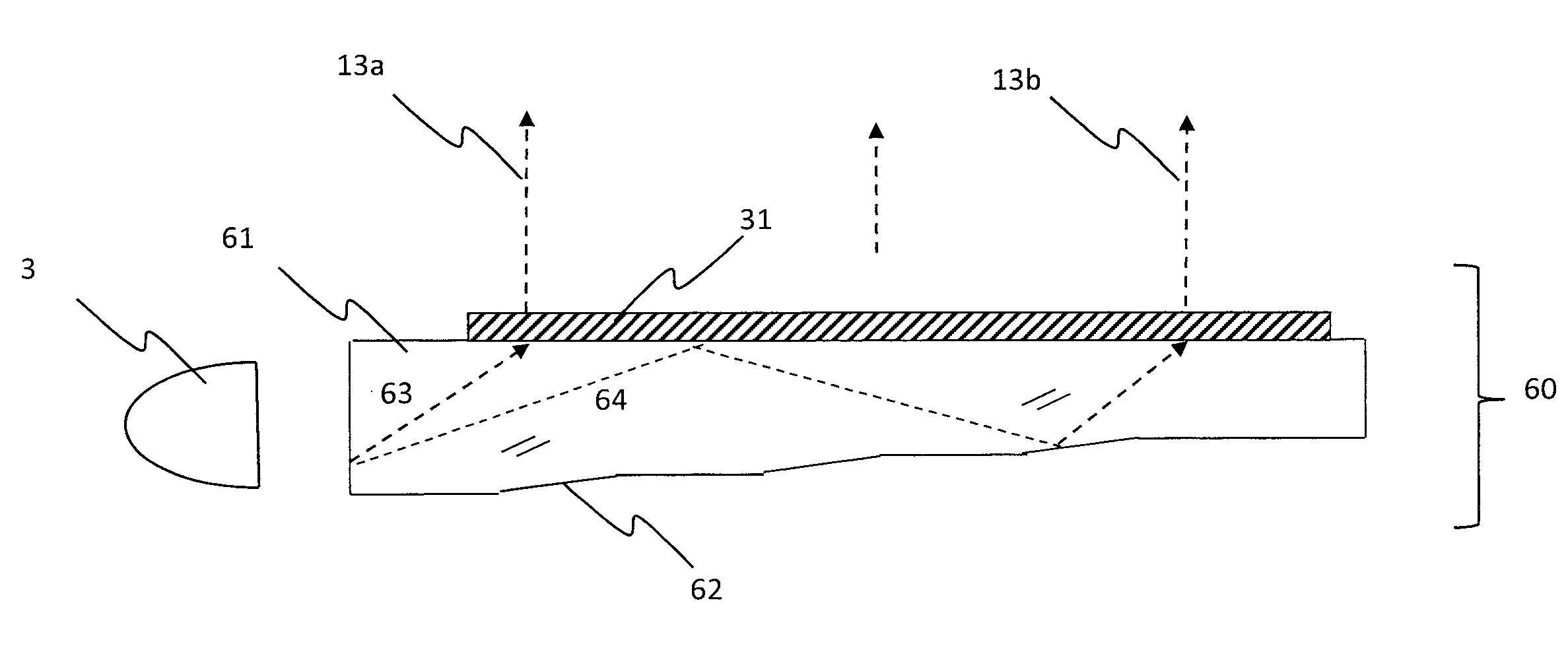
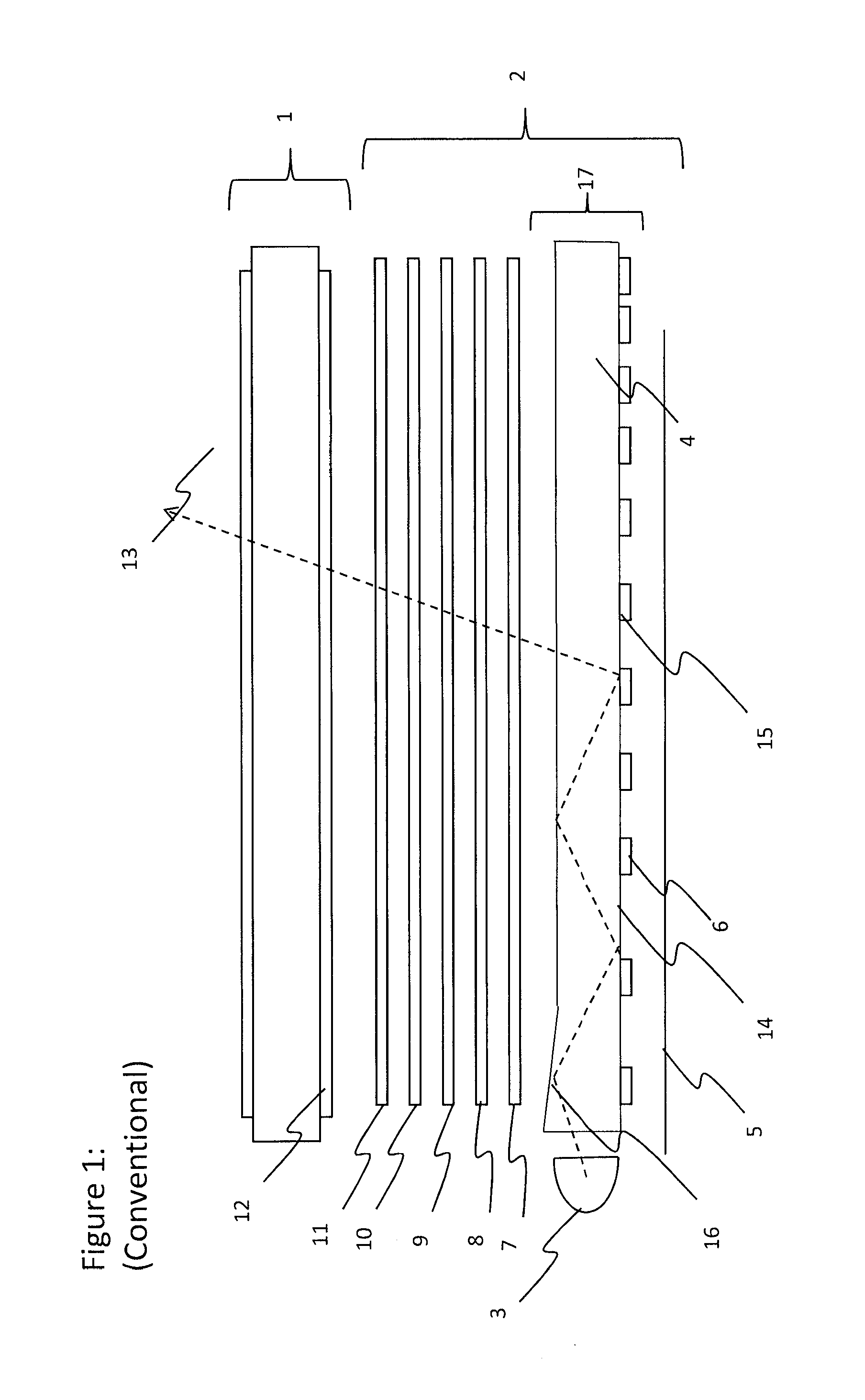
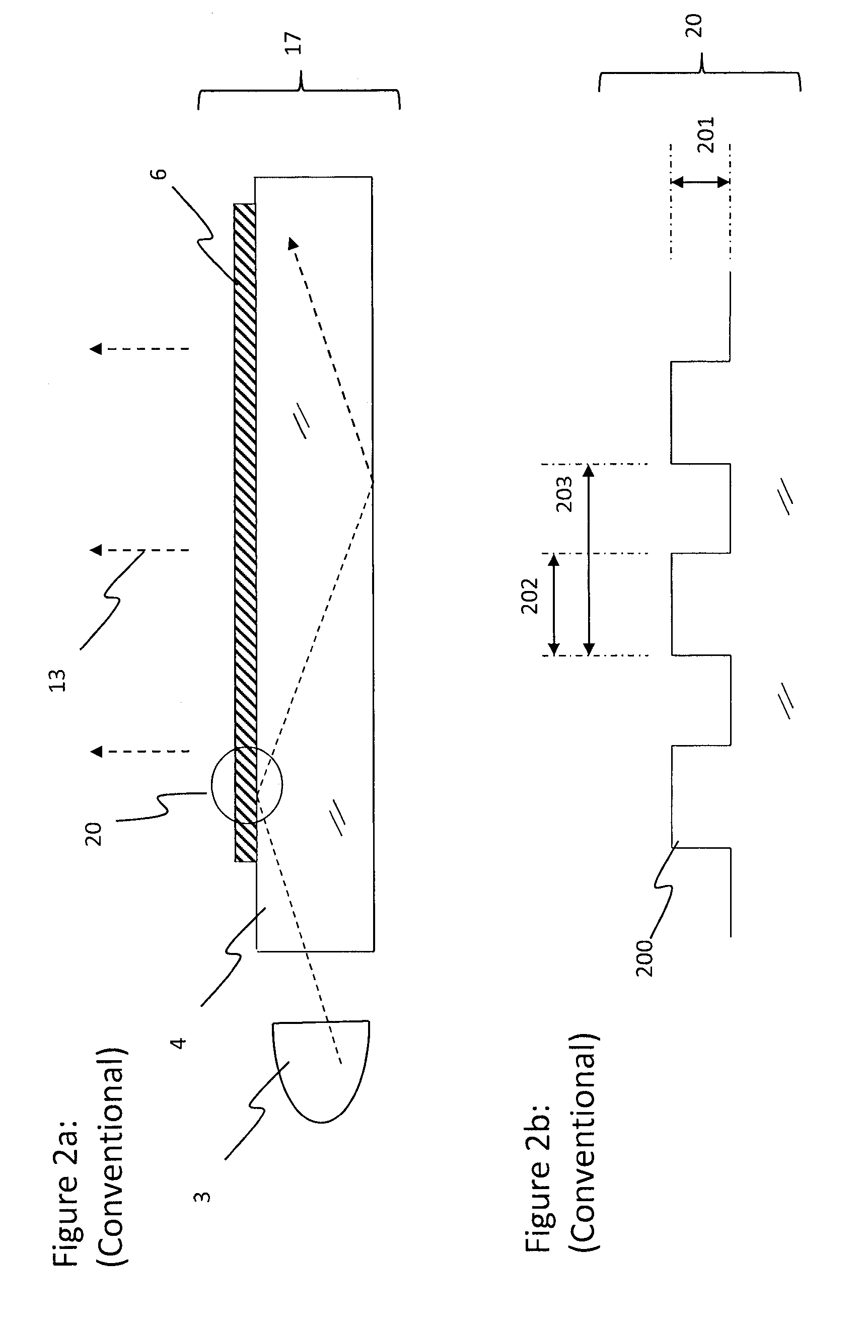
[0050]FIG. 1 illustrates a conventional small area liquid crystal display. The display includes a liquid crystal display panel 1 and a backlight unit 2. A white light source 3, which can be a fluorescent tube, a LED with phosphor, RGB LED group, a laser or other light source, is positioned to inject light into the edge of a thin lightguide 4. The lightguide 4 is designed to transfer by total internal reflection (TIR) 14 the light across the area of the display. The lightguide 4 may have a taper 16 on one of the larger sides near the light sources to allow a thinner lightguide. At least one large face, which can be the top, bottom (illustrated) or both faces, has features 6 that disrupt the TIR 14 in the lightguide so that the light 13 leaves the lightguide. The light that leaves the lightguide generally has the wro...


PUM

PropertyMeasurementUnit
sizeaaaaaaaaaa
heightaaaaaaaaaa
widthaaaaaaaaaa

Abstract

A backlight is provided for illuminating an at least partially transmissive display. The backlight includes a light source. A light guide receives the light from an edge surface and guides the light by total internal reflection. The light is extracted from the lightguide using sub-wavelength extraction features designed on the basis of one grating structure with a second interlinks structure cut into the first structure. The first structure determines the extraction properties. The second structure determines the extraction efficiency and uniformity of the system. Higher efficiency and more uniform sub-wavelength extraction are possible with a device in accordance with the invention.

Description

TECHNICAL FIELD[0001]The present invention relates to a backlight, for example, for use with an at least partially transmissive spatial light modulator. The present invention also relates to a display including such a backlight, and to a distributed illumination panel that may be used for general illumination. More particularly, the invention relates to an apparatus and method for maintaining uniformity of light provided by a lightguide and ensuring that a substantial fraction of light is extracted from the lightguide in a single pass.BACKGROUND OF THE INVENTION[0002]FIG. 1 of the accompanying drawings illustrates the stack structure of a typical liquid crystal display (LCD) module of small size, for example for a mobile phone or PDA device. The display comprises a flat transmissive spatial light modulator (SLM) in the form of an LCD panel having input and output polarisers on its bottom and top sides. The rest of the structure is generally regarded as the backlight system, as follo...

Claims


Application Information

Patent Timeline
Patent Type & Authority Applications(United States)
IPC IPC(8): G02F1/1335F21V7/04
CPCG02B6/0035G02B6/0048G02B6/0038G02B6/0061G02B6/0065
Inventor PAPAKONSTANTINOU, IOANNISMONTGOMERY, DAVID J.
Owner SHARP KK
Why Eureka
Try Eureka