X-ray system with efficient anode heat dissipation

a heat dissipation system and x-ray tube technology, applied in x-ray tubes, tomography, applications, etc., can solve the problems of difficult realization of micro-vacuum systems with motors, difficult reliability, and thermal problems of miniaturized x-ray sources, so as to achieve increased heat dissipation area and higher x-ray power

Inactive Publication Date: 2011-03-03
KONINKLIJKE PHILIPS ELECTRONICS NV
View PDF16 Cites 43 Cited by
  • Summary
  • Abstract
  • Description
  • Claims
  • Application Information

AI Technical Summary

Benefits of technology

[0014]In view of this object, a first exemplary embodiment of the present invention is directed to an X-ray scanner system comprising an array of spatially distributed, sequentially switchable X-ray sources, said X-ray sources being addressed by a programmable switching sequence with a given switching frequency, wherein each X-ray source comprises an anode with a planar X-radiation emitting surface inclined by an acute angle with respect to a plane normal to the direction of an incoming electron beam impinging on said anode at the position of a focal spot and at least one integrated actuator unit for performing at least one translational and / or rotational displacement movement of the anode relative to at least one stationary electron beam emitting cathode used for generating said electron beam. Thereby, said at least one integrated actuator unit may e.g. be given by a piezo crystal actuator which generates a mechanical stress or strain when an electric field is applied to it and thus moves the anode in a certain direction. As an alternative thereto, any other types of actuators can also be applied, of course, such as e.g. mechanical, motor-driven, electrostatic, magnetic, hydraulic or pneumatic actuators. In this way, the heated area is increased and a higher X-ray power at the output of the X-ray sources is possible.
[0015]According to the present invention, an actuator control unit may be foreseen which controls the size, direction, speed and / or acceleration of the anode's translational and / or rotational displacement movement performed by the at least one integrated actuator unit dependent on the deviation of the anode temperature at the focal spot position from a nominal operation temperature. This actuator control unit may thereby be adapted for controlling the size, direction, speed and / or acceleration of the anode's translational and / or rotational displacement movement performed by the at least one integrated actuator unit dependent on the switching frequency for sequentially switching said X-ray sources such that an image acquisition procedure executed by means of said X-ray scanner system yields a set of 2D projection images which allows an exact 3D reconstruction of an image volume of interest without blurring or temporal aliasing artifacts.
[0021]By moving the focal spot outwards while moving the whole X-ray source in a compensating manner in order to keep the position of the X-ray beam constant in relation to the gantry and the detector, the heat capacity of the X-ray source can be increased. Electron beam deflection thereby enlarges the volume of heat spread of the focal spot track and improves the instantaneously available heat capacity.
[0025]In other words, it may be foreseen to increase the heat capacity of an X-ray source by moving its focal spot outwards while simultaneously moving the whole tube in a compensating manner in order to keep the position of the X-ray beam constant in relation to the X-ray scanner system's gantry and the particular detector attached to said gantry. The movement of the electron beam enlarges the volume of heat spread of the focal spot track and thus improves the instantaneously available heat capacity.

Problems solved by technology

But even a miniaturized X-ray source would face the thermal problem mentioned above.
Aside therefrom, the reliability could be an issue as micro-vacuum systems with motors are not easy to realize (even though being possible and also an alternative).

Method used


Image

  • X-ray system with efficient anode heat dissipation
  • X-ray system with efficient anode heat dissipation
  • X-ray system with efficient anode heat dissipation

Examples


Embodiment Construction

[0044]In the following, the X-ray scanner system according to an exemplary embodiment of the present invention will be explained in more detail with respect to special refinements and referring to the accompanying drawings.

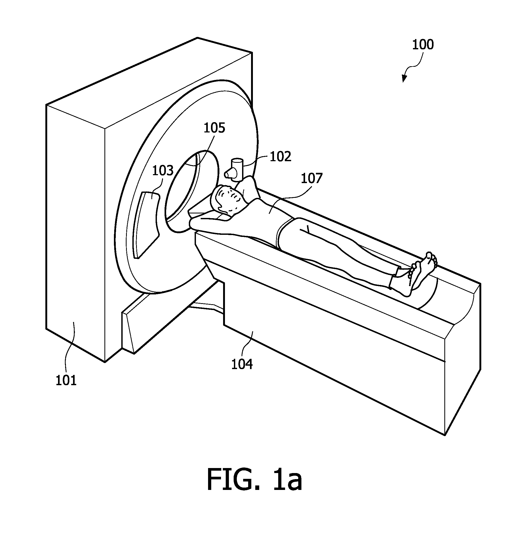
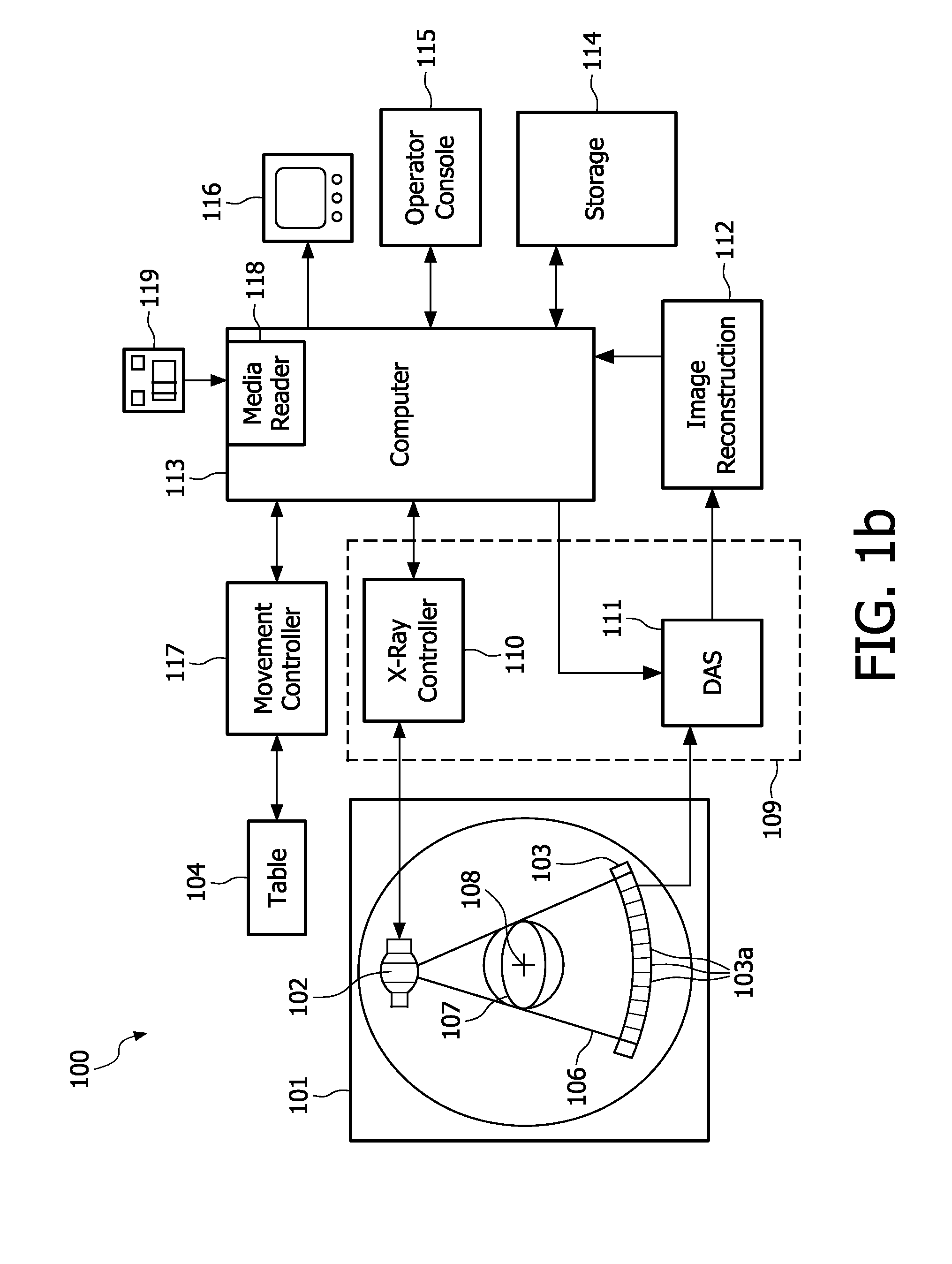
[0045]FIG. 1a shows a configuration of a CT imaging system as known from the prior art. In current CT imaging systems such as depicted in FIG. 1a, an X-ray source 102 mounted on a rotational gantry 101 rotates about the longitudinal axis 108 of a patient's body 107 or any other object to be examined while generating a fan or cone beam of X-rays 106. An X-ray detector array 103, which is usually mounted diametrically opposite to the location of said X-ray source 102 on said gantry 101, rotates in the same direction about the patient's longitudinal axis 108 while converting detected X-rays, which have been attenuated by passing the patient's body 107, into electrical signals. An image rendering and reconstruction system 112 running on a computer or workstation 113 t...


PUM


Abstract

X-ray systems for use in high-resolution imaging applications with an improved power rating are provided. An X-ray source comprises at least one integrated actuator unit (206, 206′, 206a or 206b) for performing at least one translational and / or rotational displacement by moving the position of the X-ray source's anode (204, 204′, 204a′ or 204b′) relative to a stationary reference position. This helps to overcome power limitations due to an overheating of the anode at its focal ̂spot position (205). In addition to that, a focusing unit (203) for allowing an adapted focusing of the anode's focal spot (205) which compensates deviations in the focal spot size resulting from said anode displacements and / or a deflection means (211, 21 Ia or 21 Ib) for generating an electric and / or magnetic field deflecting the electron beam (202, 202a or 202b) in a direction opposite to the direction of the rotary anode's displacement movement may be provided.

Description

[0001]The present invention refers to X-ray systems for use in high-resolution imaging applications with an improved power rating and, more particularly, to a variety of system configurations for an X-ray based image acquisition system using an X-ray source of the rotary anode type or, alternatively, an array of spatially distributed X-ray sources fabricated in carbon nanotube (CNT) technology, thus allowing higher sampling rates for an improved temporal resolution of acquired CT images as needed for an exact reconstruction of fast moving objects (such as e.g. the myocard) from a set of acquired 2D projection data. According to the present invention, each X-ray source comprises at least one integrated actuator unit for performing at least one translational and / or rotational displacement by moving the position of the X-ray source's anode relative to a stationary reference position, wherein the latter may e.g. be given by a mounting plate or an electron beam emitting cathode which pro...

Claims


Application Information

Patent Timeline
Patent Type & Authority Applications(United States)
IPC IPC(8): H05G1/70H01J35/24B82Y99/00
CPCA61B6/032A61B6/4028A61B6/4085A61B6/4021H01J35/14H01J35/26H01J35/30A61B6/4488H01J35/28H01J35/147H01J35/153
Inventor VOGTMEIER, GEREONPIETIG, RAINERLEWALTER, ASTRIDBEHLING, ROLF KARL OTTO
Owner KONINKLIJKE PHILIPS ELECTRONICS NV
Why Eureka
Try Eureka