Proactive load distribution for 802.111-based wireless lans

a wireless lan and active load technology, applied in the field of active load distribution of 802.111-based wireless lans, to achieve the effect of improving quality of connection, less interference, and more available rf resources

Active Publication Date: 2011-03-10
AVAYA INC
View PDF9 Cites 36 Cited by
  • Summary
  • Abstract
  • Description
  • Claims
  • Application Information

AI Technical Summary

Benefits of technology

[0007]The embodiments quickly assess when a quality threshold is crossed. Then, the wireless LAN controller algorithms can force handoffs of communications sessions to better access points with more available RF resources or less interference. A technique to avoid over-acceptance during periods of high call request rates, full bandwidth is assumed to be used immediately upon call acceptance. Over time, the calculated bandwidth usage decays to the measured bandwidth usage according to a configurable time constant. Similarly, if the measurement system detects a sharp increase in bandwidth usage due to some type of interference (i.e., a physical barrier or noise), then the system ensures that new admission decisions are made based on the updated usage. The result is a seamless method for maintaining good quality connections with mobile devices.
[0008]Further, the embodiments can manage different classes of data differently. Voice and Video communications are handled differently than data communications. The embodiments handle the distribution of video and voice communications separately from data communications. The embodiments also proactively distribute loads. Proactive load distribution is tunable based on predetermined thresholds to determine how early to begin load balancing. Proactive load balancing is most useful for users with clusters of overloaded access points. In an example of proactive load balancing, there may be one or more access points at points or areas of high demand. One or more other access points may be concentrically distributed, in ever increasing distances, around the access point experiencing high demand. Proactive load balancing can shift load away from the high-demand access point at the center of the high demand area to access points outside the center of high demand. Further, the load can be shifted in anticipation of any bandwidth requirements or limitations to accept load from the central point of ...

Problems solved by technology

The result is a seamless method for maintai...

Method used


Image

  • Proactive load distribution for 802.111-based wireless lans
  • Proactive load distribution for 802.111-based wireless lans
  • Proactive load distribution for 802.111-based wireless lans

Examples


Embodiment Construction

[0031]The ensuing description provides embodiments only, and is not intended to limit the scope, applicability, or configuration of the claims. Rather, the ensuing description will provide those skilled in the art with an enabling description for implementing the embodiments. It should be understood that various changes may be made in the function and arrangement of elements without departing from the spirit and scope of the appended claims.

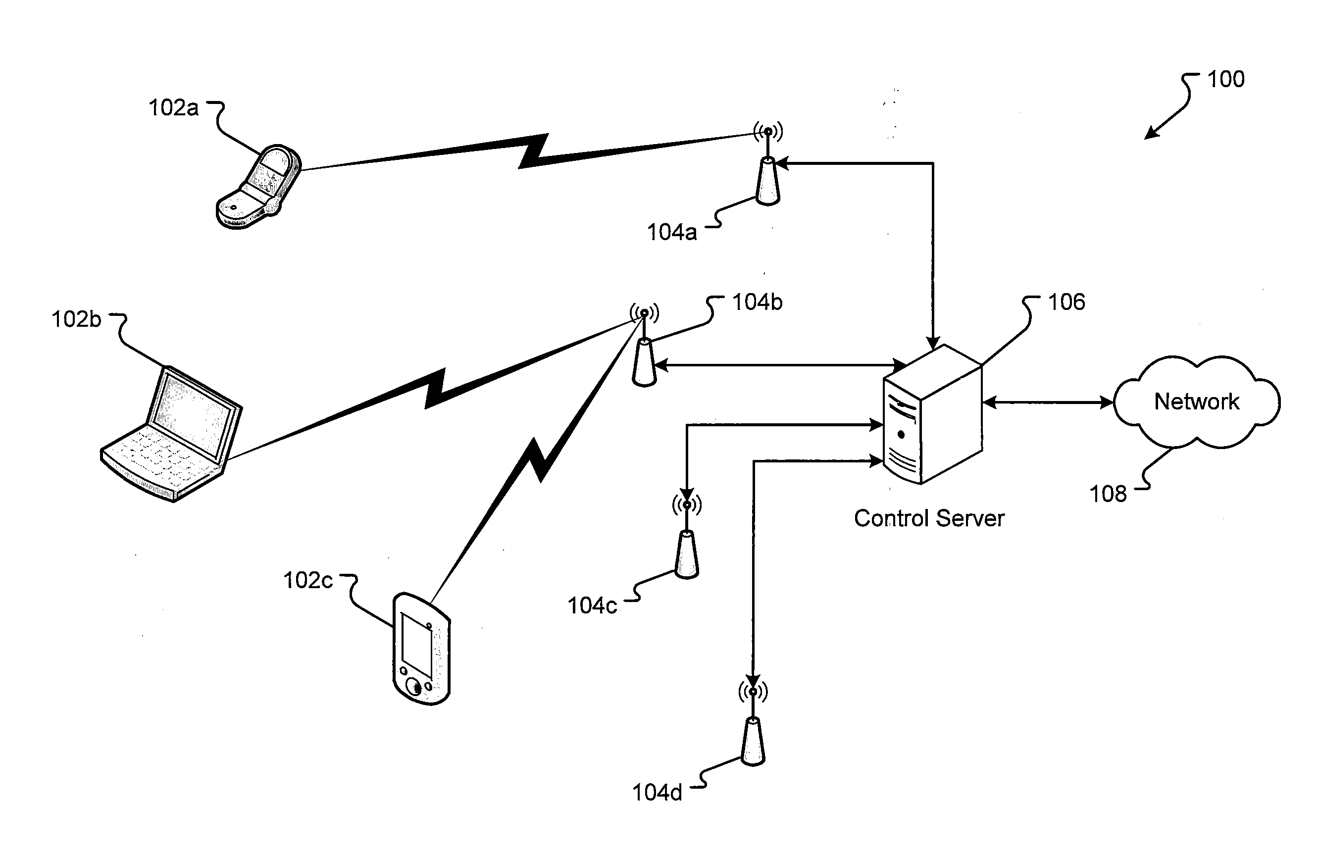
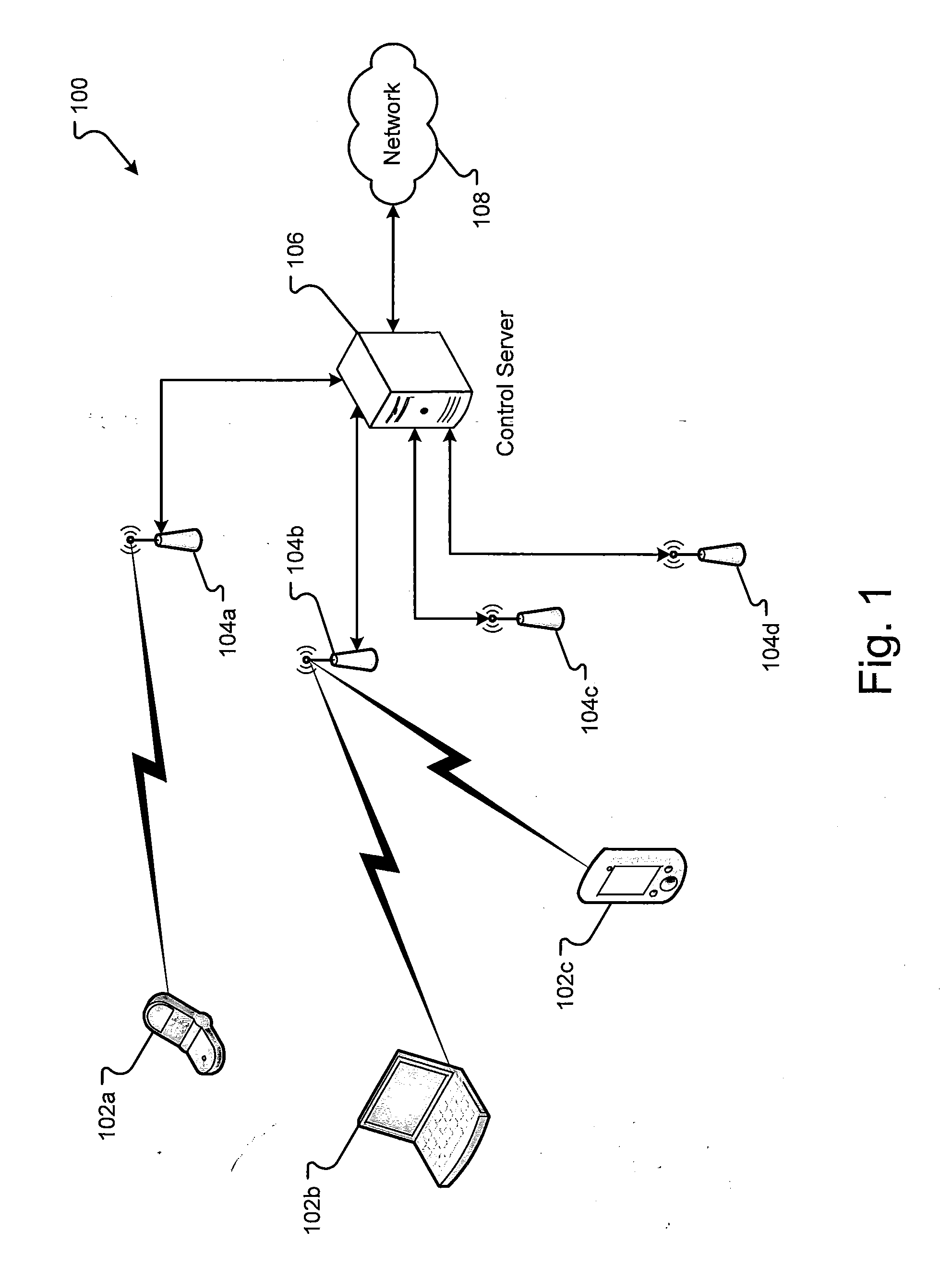
[0032]A communication system 100 for determining the admission of a communication session to an access point 104 is shown in FIG. 1. Communication system 100 can include at least one mobile device 102a, 102b and / or 102c, at least one wireless access point 104a, 104b, 104c, and / or 104d, and at least one control server 106. The communication system 100 can have more or, fewer mobile devices 102, access points 104, or control servers 106 than those shown in FIG. 1. The communication system 100 of FIG. 1 is provided only as an example to help describ...


PUM


Abstract

A wireless communication system is able to balance load in a wireless network based on radio frequency (RF) utilization, signal strength, quality of signal (QoS), and other measures. The load may be dynamically moved to other wireless access points within the wireless network based on the amount of load on one or more of the access points and on the measures. As such, at different load conditions, the system can change the methods of how to determine which access point should handle a communication session. Further, the system provides methods for proactively adjusting the load in the wireless network before any one access point reaches its capacity.

Description

CROSS REFERENCE[0001]This application claims priority to U.S. Provisional Application Ser. No. 61 / 156,994 filed Mar. 3, 2009, entitled “A Practical Measurement-Based Session Admission Control for Wi-Fi LAN Systems,” which is incorporated herein by reference in its entirety, and is related to U.S. application Ser. No. ______, filed Mar. 2, 2010, entitled “Practical Measurement-Based Session Admission Control for Wi-Fi LAN Systems,” which is incorporated herein by reference in its entirety.BACKGROUND[0002]Improving the quality of service for voice over internet protocol (VoIP) over wireless Local Area Networks (LANs) is on the critical path to achieving the vision of the unwired enterprise. Achieving high quality VoIP poses several challenges, particularly in heavily loaded systems. Wireless systems generally use signal strength as the determinant factor for which wireless access point should accept a communication session with a mobile device. In many situations, a small number of ac...

Claims


Application Information

Patent Timeline
IPC IPC(8): H04W28/08
CPCH04W28/08H04W28/0958H04W28/0861
Inventor KRYM, MARVINBABIARZ, JOZEFVERBERK, LAMBERTUSXU, KENANWU, PING
Owner AVAYA INC
Why Eureka
Try Eureka