Positive electrode active material, positive electrode, nonaqueous electrolyte cell, and method of preparing positive electrode active material

a technology of active materials and positive electrodes, which is applied in the direction of cobalt compounds, chemistry apparatus and processes, cell components, etc., can solve the problems of increasing resistance of electrodes, lowering capacity due to coating, and difficult to obtain sufficient capacity, so as to achieve sufficient capacity, reduce the effect of capacity and increase the resistance of electrodes

Active Publication Date: 2011-03-10
MURATA MFG CO LTD
View PDF11 Cites 32 Cited by
  • Summary
  • Abstract
  • Description
  • Claims
  • Application Information

AI Technical Summary

Benefits of technology

[0009]However, according to the addition of an metallic salt or hydroxide to a lithium-transition metal oxide having a normal uniform form as in the method of Patent Document 1, the resistance of the electrode increased and it was very difficult to obtain a sufficient capacity. In the method of Patent Document 2, the lowering in capacity due to the coating was so large that the positive electrode active material was unsatisfactory for practical use. The method of Patent Documents 3 and 4 was unsatisfactory as a technique for enhancing cell performance in high-temperature environments, if use is made of only the coating element, coating method, and coating form disclosed in the document. Besides, it was found that increasing the coating amount in order to obtain a sufficient effect leads to hindrance of diffusion of lithium ions, making it very difficult to obtain a sufficient capacity at charge-discharge current values in practical-use ranges. Thus, the method was found unsatisfactory.

Problems solved by technology

However, according to the addition of an metallic salt or hydroxide to a lithium-transition metal oxide having a normal uniform form as in the method of Patent Document 1, the resistance of the electrode increased and it was very difficult to obtain a sufficient capacity.
In the method of Patent Document 2, the lowering in capacity due to the coating was so large that the positive electrode active material was unsatisfactory for practical use.
The method of Patent Documents 3 and 4 was unsatisfactory as a technique for enhancing cell performance in high-temperature environments, if use is made of only the coating element, coating method, and coating form disclosed in the document.
Besides, it was found that increasing the coating amount in order to obtain a sufficient effect leads to hindrance of diffusion of lithium ions, making it very difficult to obtain a sufficient capacity at charge-discharge current values in practical-use ranges.
Thus, the method was found unsatisfactory.
The method disclosed in Patent Document 4 to 9 was found unsatisfactory for enhancing cycle characteristics to a high extent and suppressing a rise in resistance during high-temperature use, though a high capacity can be maintained by the method.
When a positive electrode active material was prepared by the method and structure disclosed in Patent Document 12, it was very difficult to obtain a sufficient charge-discharge efficiency, and the capacity was largely lowered.
Besides, when the positive electrode active material was actually prepared by the method disclosed in the document, a uniform multiple layer was formed, and the effect was not recognized, particularly, on a rise in resistance during high-temperature use.
As for the approach according to Patent Document 15, mere coating with a metallic fluoride being low in electronic conductivity and lithium ion conductivity resulted in a conspicuous lowering in charge-discharge performance, and its effect on charge-discharge characteristics in high-temperature environments was insufficient.
In addition, it was very difficult to obtain charge-discharge performance on a practical-use level, because the migration of lithium ions at the charge-discharge times was hampered at the solid-liquid interface.
Besides, there was also observed a tendency of lowering in capacity, because lithium was deprived from the lithium-transition metal composite oxide.
Thus, the material according to the document was unsatisfactory.

Method used


Image

  • Positive electrode active material, positive electrode, nonaqueous electrolyte cell, and method of preparing positive electrode active material
  • Positive electrode active material, positive electrode, nonaqueous electrolyte cell, and method of preparing positive electrode active material
  • Positive electrode active material, positive electrode, nonaqueous electrolyte cell, and method of preparing positive electrode active material

Examples


first embodiment

1. First Embodiment

First Example of Nonaqueous Electrolyte Cell

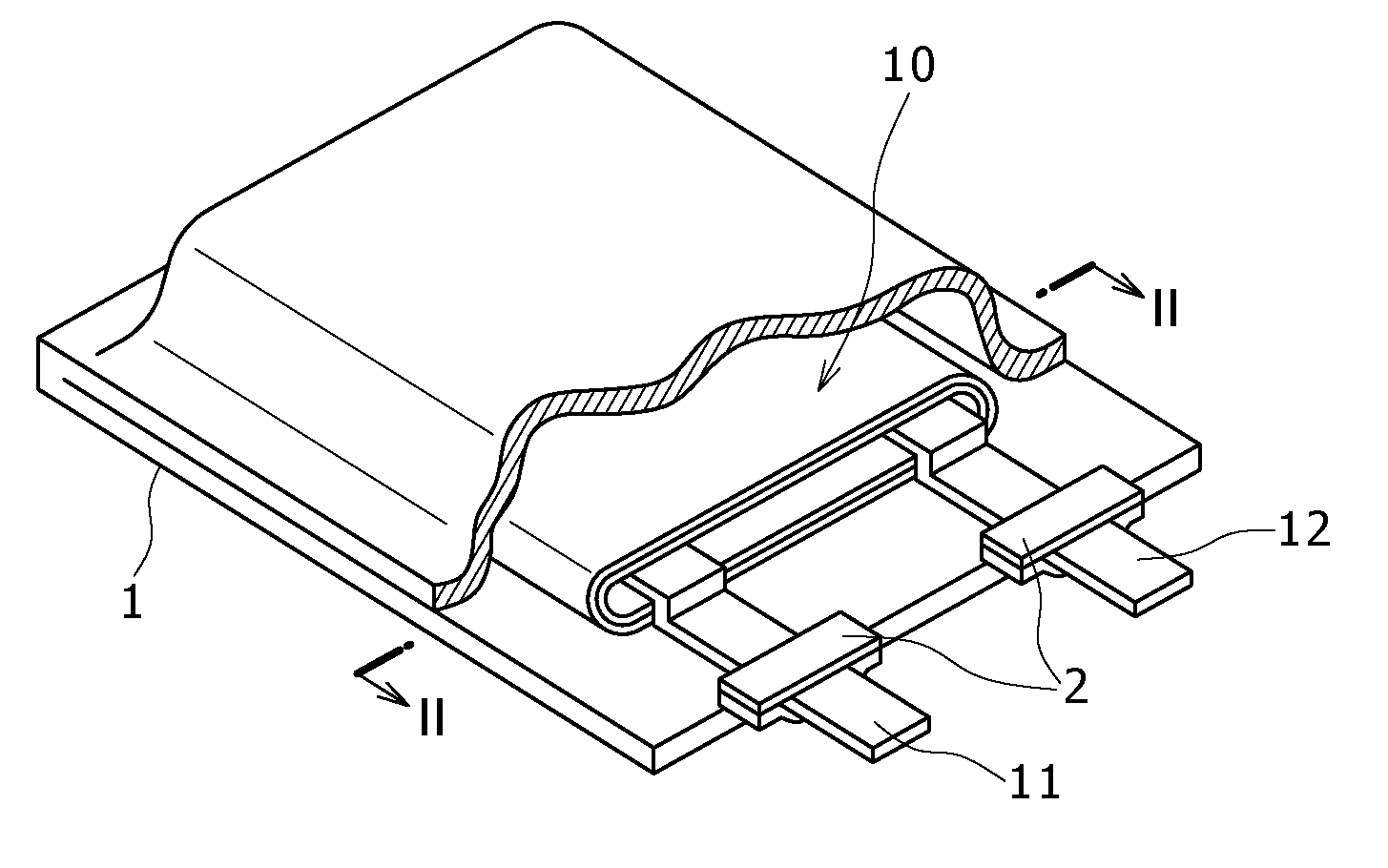
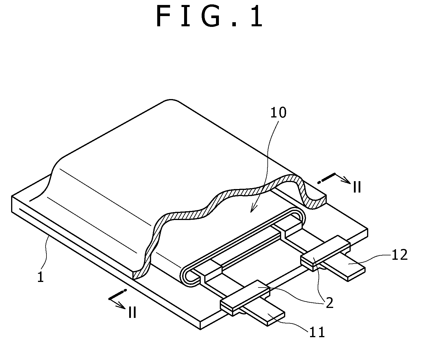
[0063]FIG. 1 is a perspective view showing a configuration example of a nonaqueous electrolyte cell according to a first embodiment. The nonaqueous electrolyte cell is, for example, a nonaqueous electrolyte secondary cell. The nonaqueous electrolyte cell, flat in overall shape, has a configuration in which a wound electrode body 10 fitted with a positive electrode lead 11 and a negative electrode lead 12 is accommodated in the inside of film formed casing members 1.

[0064]The positive lead 11 and the negative lead 12 are each, for example, rectangular plate-like in shape, and they are lead out from the inside toward the outside of the casing members 1 in the same direction, for example. The positive electrode lead 11 is made of a metallic material such as aluminum (Al), for example, and the negative electrode lead 12 is made of a metallic material such as nickel (Ni), for example.

[0065]The casing members 1 are each compos...

second embodiment

2. Second Embodiment

Second Example of Nonaqueous Electrolyte Cell

[0126]A second embodiment will be described. A nonaqueous electrolyte cell according to the second embodiment uses positive active material with more uniformly coating.

[0127]Since other materials and configurations are the same as in the first embodiment, the explanations about these are omitted.

[0128]Positive Electrode Active Material

[0129]The positive electrode active material is, for example, composite oxide particles which contain therein a metallic element M2 different from a principal transition metal M1 and which have a concentration gradient of the metallic element M2 from the center toward the surface of each particle. The concentration gradient is such that the concentration of the metallic element M2 increases as the particle surface is approached. The composite oxide particles are particles of a lithium-containing transition metal composite oxide wherein at least one element X selected from among sulfur (S)...

third embodiment

3. Third Embodiment

Third Example of Nonaqueous Electrolyte Cell

[0146]A second embodiment will be described. A nonaqueous electrolyte cell according to the second embodiment uses an electrolytic solution in place of the gelled electrolyte 16 in the nonaqueous electrolyte cell according to the first embodiment. In this case, the electrolytic solution is used by impregnating the separator 15 therewith. As the electrolytic solution, the same electrolytic solutions as those in the first embodiment above can be used.

[0147]The nonaqueous electrolyte cell thus configured can be manufactured, for example, in the following manner. First, the positive electrode 13 and the negative electrode 14 are produced. The positive electrode 13 and the negative electrode 14 can be produced in the same manner as in the above-described first embodiment, and, therefore, detailed description of the production is omitted here.

[0148]Next, after the positive electrode lead 11 and the negative electrode lead 12 a...


PUM

PropertyMeasurementUnit
melting pointaaaaaaaaaa
diameteraaaaaaaaaa

Abstract

Disclosed herein is a positive electrode active material prepared by mixing a lithium-containing compound, a compound containing a transition metal to be put into a solid solution, and a compound containing a metallic element M2 different from the transition metal, and firing the mixture to form composite oxide particles, depositing a compound containing at least one element selected from among sulfur (S), phosphorus (P) and fluorine (F) on surfaces of the particles, and firing the particles, whereby each of the particles is provided with a concentration gradient such that the concentration of the metallic element M2 increases from the center toward the surface of the particle, and at least one element selected from among (S), (P) and (F) is made present in the form of being aggregated at the surfaces of the composite oxide particles.

Description

CROSS REFERENCES TO RELATED APPLICATIONS[0001]The present application claims priority to Japanese Priority Patent Applications JP 2009-208505, 2010-105024, 2009-263301, and 2010-105025 filed in the Japan Patent Office on Sep. 9, 2009, Apr. 30, 2010, Nov. 18, 2009, and Apr. 30, 2010, respectively, the entire content of which is hereby incorporated by reference.BACKGROUND[0002]The present application relates to a positive electrode active material, a positive electrode, a nonaqueous electrolyte cell, and a method of preparing a positive electrode active material. More particularly, the application relates to a positive electrode active material, a positive electrode, a nonaqueous electrolyte cell, and a method of preparing a positive electrode active material by which to realize a nonaqueous electrolyte cell having high performance and showing little capacity deterioration when subjected to charging and discharging in high-temperature environments. In detail, the present application r...

Claims


Application Information

Patent Timeline
Patent Type & Authority Applications(United States)
IPC IPC(8): H01M4/505H01M4/48
CPCC01G51/006H01M4/483C01P2002/50C01P2002/52C01P2004/20C01P2004/54C01P2004/61C01P2004/80C01P2006/40H01M4/131H01M4/1315H01M4/1391H01M4/485H01M4/505H01M4/525H01M10/052H01M2004/021Y02E60/122H01M4/0402H01M4/366C01G51/42Y02E60/10
Inventor MORITA, KOJIHOSOYA, YOSUKEFUJIKI, SATOSHIMOTOHASHI, KAZUNARILI, GUOHUAENDOH, KAZUAKI
Owner MURATA MFG CO LTD
Why Eureka
Try Eureka