Upconverter

Active Publication Date: 2011-03-10
SIEMENS HEALTHCARE GMBH
View PDF20 Cites 16 Cited by
  • Summary
  • Abstract
  • Description
  • Claims
  • Application Information

AI Technical Summary

Benefits of technology

[0014]Preferably, the additional drain loading reduces the output impedance to a value of the order of 270Ω.
[0015]Damping the output impedance to of the order of 270Ω,

Problems solved by technology

These add cost and inconvenience to the structure.
In use, the requirement to connect the cables and sterilise them between scanning one patient and the next leads to increased down-time between scans.
The gain and stability of parametric amplifiers is sensitive to the received level of local oscillato

Method used


Image

  • Upconverter
  • Upconverter
  • Upconverter

Examples


Embodiment Construction

[0043]The present invention addresses the problem of variation of incident local oscillator level encountered when using parametric amplifiers in the confines of the multiply illuminated scanner bore, where various multipath effects lead to significant variation in the path loss between the bore mounted LO sources and the patient coil mounted parametric amplifiers.

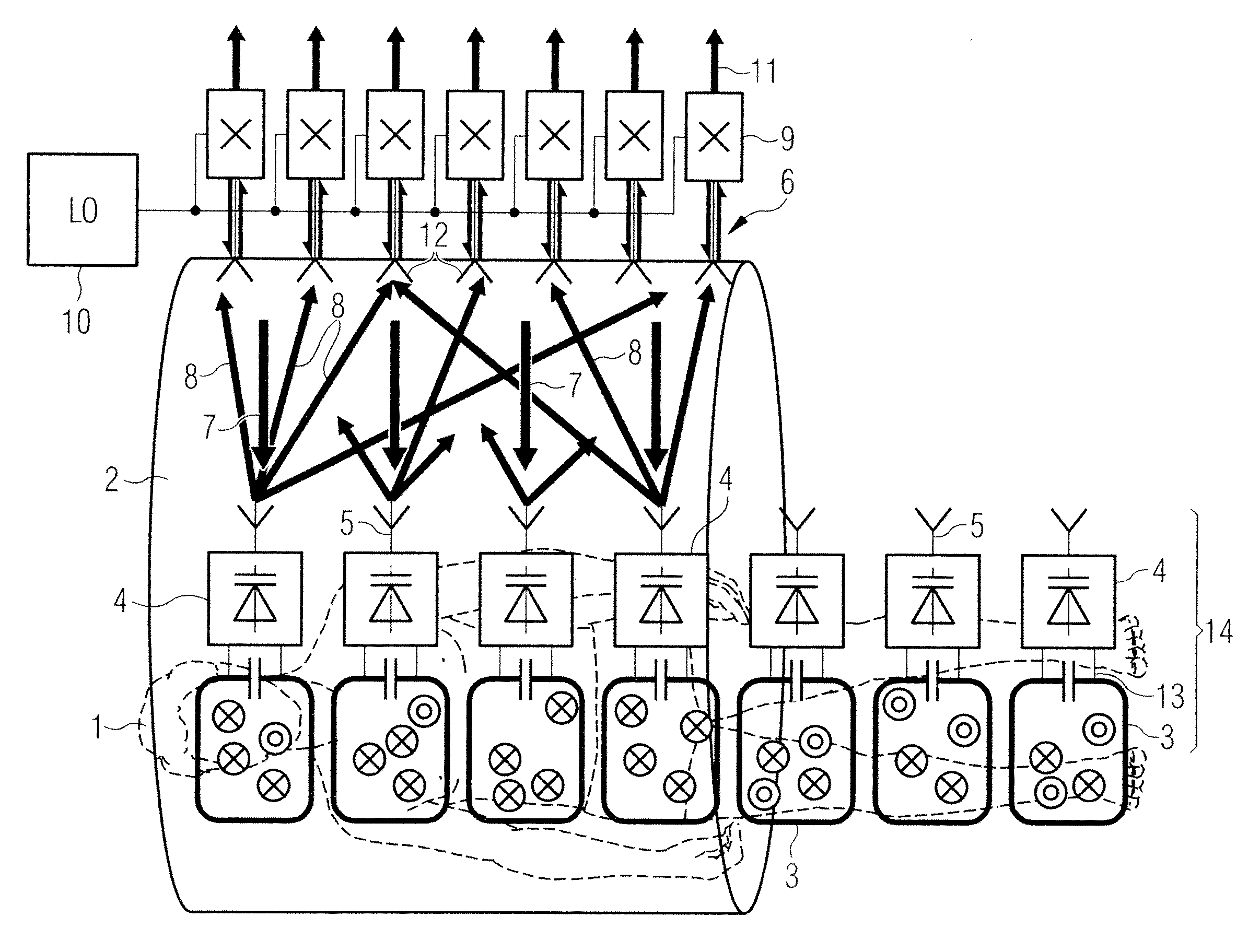
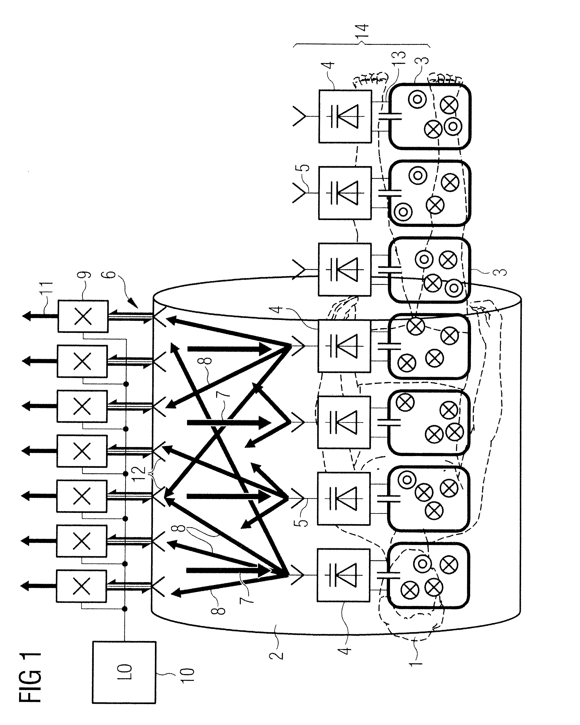
[0044]An example of an MRI system using a MIMO microwave link, in which parametric amplifier devices in accordance with the present invention are used, will now be described. FIG. 1 shows a patient 1 within an MRI scanner bore tube 2. A mat covers the part of the patient for imaging and embedded in the mat are a plurality of local coils 3. Associated with each local coil 3 is an upconverter stage 4 and microwave antenna 5. Transceivers 9, connected to an array 6 of antennas 12, are integrated into the scanner bore 2. A parametric amplifier circuit in the upconverter carries out the mixing and amplification necessary for up...


PUM


Abstract

A hybrid upconverter has a low noise amplifier and a two port parametric amplifier. The parametric amplifier has a first port to receive an input signal to be amplified and upconverted and a second port to receive a local oscillator signal and to output the amplified, upconverted signal at upper and lower sideband frequencies. The parametric amplifier further has an antenna coupled to the second port to receive the local oscillator signal and transmit the amplified, upconverted signal at upper and lower sideband frequencies. The low noise amplifier drives the first port of the parametric amplifier. The two port parametric amplifier has a pair of varactor diodes connected between the first port and the second port. The diodes are connected in parallel from the first port and in series from the second port. The low noise amplifier is connected directly to the pair of varactor diodes.

Description

BACKGROUND OF THE INVENTION[0001]1. Field of the Invention[0002]This invention relates to an upconverter, in particular for use in magnetic resonance imaging (MRI).[0003]2. Description of the Prior Art[0004]MRI scanners use a combination of a strong constant magnetic field (B0) from a superconducting magnet which is modified by gradient fields generated by gradient coils, together with a rotating magnetic field (B1) from a radio frequency (RF) antenna to excite nuclear magnetic resonances in the body that generate short term RF signals that are received to build up a tomographic image.[0005]All current-generation MRI scanners employ arrays of local coils mounted in close proximity to the scanned patient to receive the RF with maximum possible signal to noise ratio (SNR). The local coils that receive signals from the back of the patient are mounted in the patient table. Local coils that receive signals from the front of the patient are arranged into ‘mats’ that are carefully placed o...

Claims


Application Information

Patent Timeline
IPC IPC(8): H04B1/26
CPCG01R33/3415H03F7/04G01R33/3692G01R33/36
Inventor CORK, PETER
Owner SIEMENS HEALTHCARE GMBH
Why Eureka
Try Eureka