Network monitoring device, bus system monitoring device, method and program

Active Publication Date: 2011-03-10
PANASONIC CORP
View PDF20 Cites 169 Cited by
  • Summary
  • Abstract
  • Description
  • Claims
  • Application Information

AI Technical Summary

Benefits of technology

[0041]According to the present invention, in a network application such as a media transmission in which the change in throughput decreases the quality of service, it is possible to find out the status of transmission path ro

Problems solved by technology

On the other hand, real-time applications such as video transfer and audio telephone are very sensitive to the change in transmission quality suc

Method used


Image

  • Network monitoring device, bus system monitoring device, method and program
  • Network monitoring device, bus system monitoring device, method and program
  • Network monitoring device, bus system monitoring device, method and program

Examples


embodiment 1

[0078]The following describes embodiments of the present invention with reference to the drawings.

first embodiment

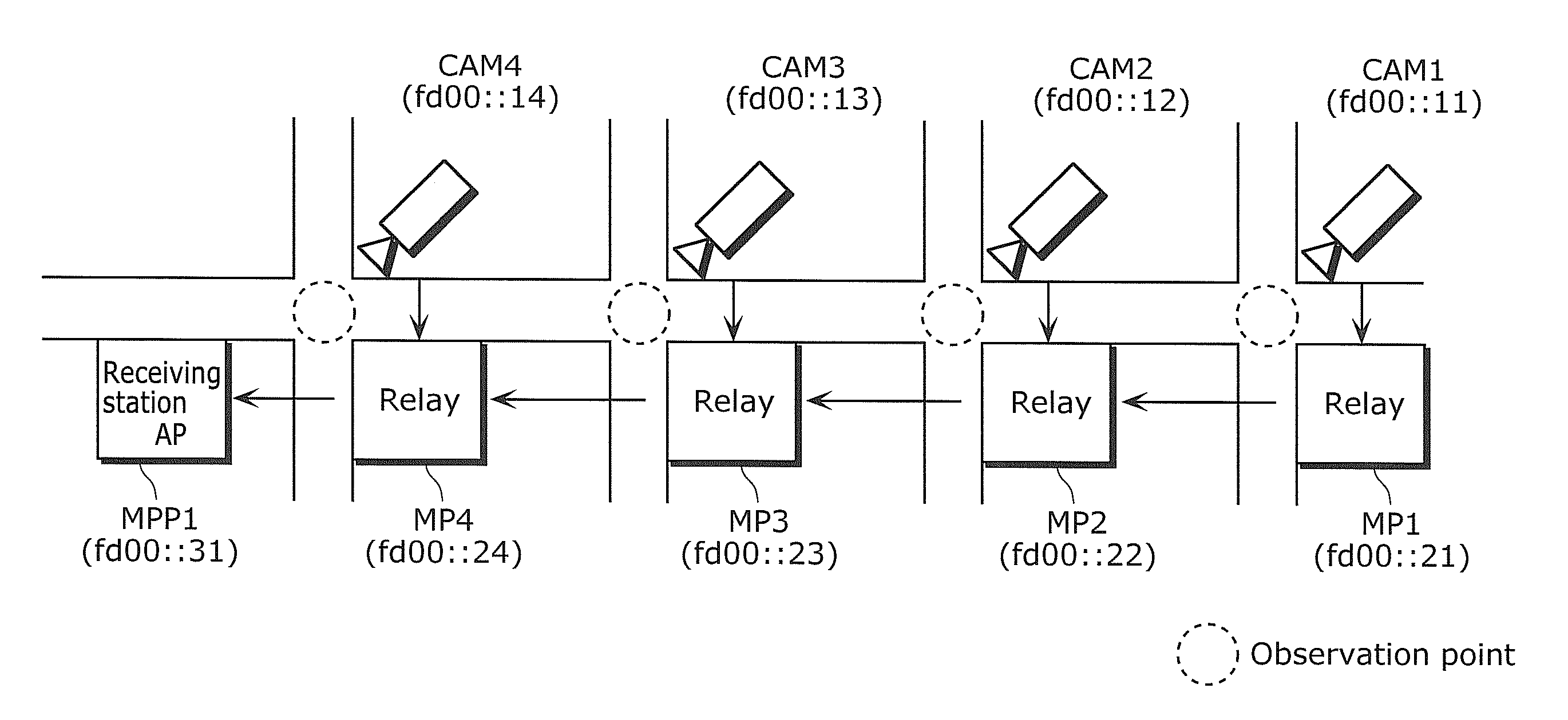
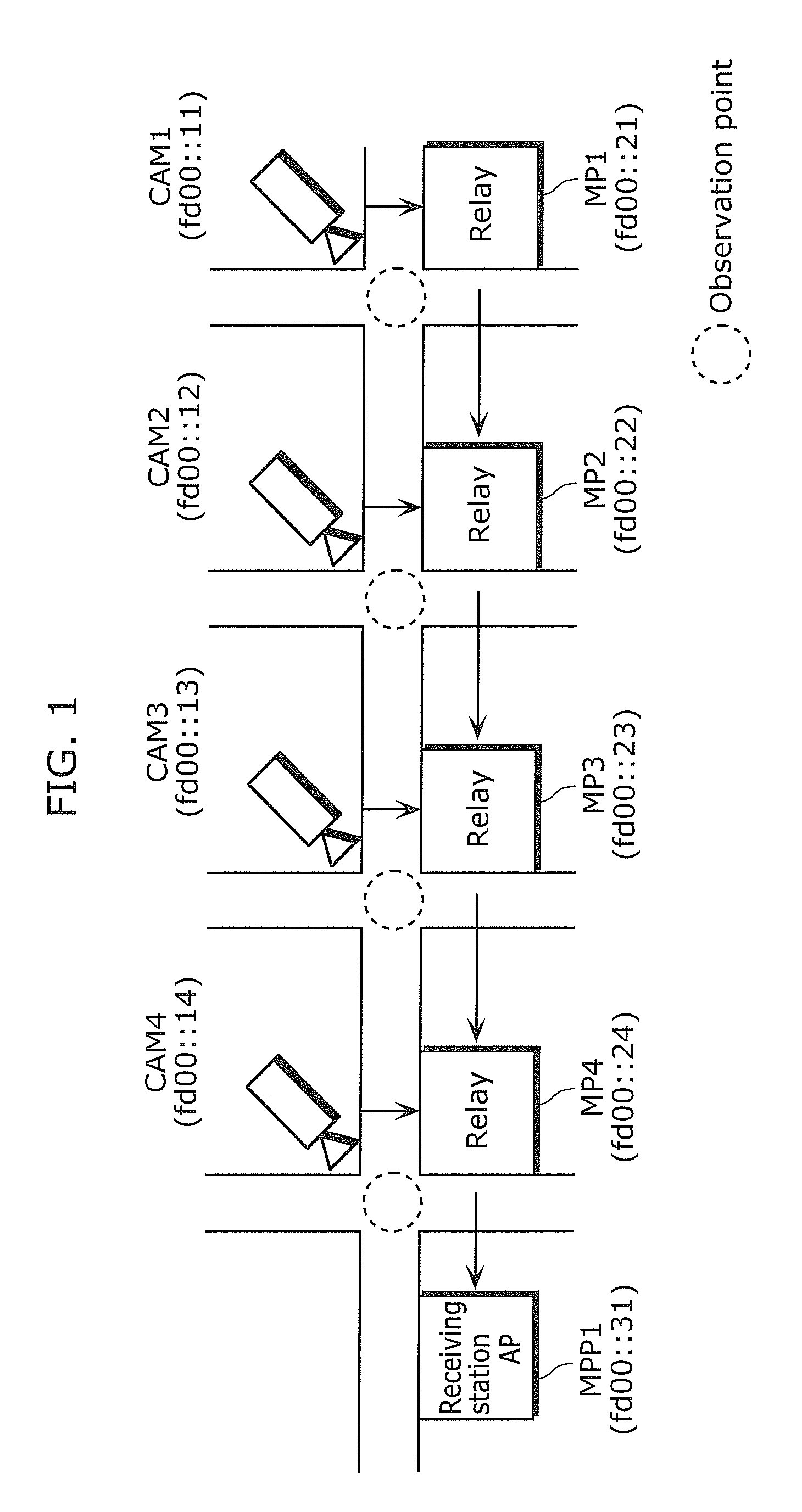
[0079]FIG. 1 is a schematic diagram illustrating the configuration of the video transfer system as an example of object to be monitored according to the first embodiment. The video transfer system includes cameras installed in areas where the monitoring for safety is necessary, such as downtown or route to and from school. The video transfer system is a type of security system that supports safety through remote monitoring performed by transmitting the video captured by the cameras to the center station through the network.

[0080]In FIG. 1, CAM1 to CAM4 are cameras installed at respective intersections for capturing video at the intersections. MP1 to MP4 are relays installed at respective intersections. MPP is an Access Point (AP) of the receiving station. The devices are connected by a wireless ad-hoc network which can be easily installed.

[0081]The capturing ranges of the cameras are shown in broken line in FIG. 1. The video at the intersections captured by the CAM1 to CAM4 is trans...

second embodiment

[0156]FIG. 17 is a block diagram illustrating the configuration of the video coding SoC according to the second embodiment, as an example of the device to be controlled by the bus system monitoring device (arbiter) according to the second embodiment of the present invention.

[0157]Generally, a scheme for processing data in video coding standardized by MPEG2 and others are roughly divided into decimation for reducing the amount of information in input video signals, preprocess for reducing noise and limiting bandwidth, motion estimation, frequency spectrum analysis, video coding for compressing information and allocating codes using visual feature, and others.

[0158]The video coding SoC illustrated in FIG. 17 is an example of multi-core architecture performing these processes by independent digital signal processors DSP1, DSP2, DSP3, DSP4, and DSP5. The DSPs are connected by video data buses VBUS2, VBUS3, VBUS4, and VBUS5, respectively.

[0159]The video data to be coded is accumulated in...


PUM


Abstract

A network monitoring device which monitors a network in which data is transmitted through relays, includes a monitoring frequency recording unit (111) which records monitoring frequencies for monitoring transmission statuses of the relays, a selection probability generating unit (112) which generates selection probability information which is probability values for the relays, a monitoring object determining unit (113) which determines, according to the monitoring frequency and the selection probability information, a relay the transmission status of which is to be monitored, a transmission status obtaining unit (106) which obtains transmission status information indicating a transmission status on the relay determined, a transmission status recording unit (107) which records the transmission status information, an activation level calculating unit (109) which calculates, using the transmission status information, activation level indicating suitability of the monitoring on the transmission statuses of the relays, and a monitoring frequency updating unit (110) which updates, based on the activation level, the monitoring frequency, and the network monitoring device detects the change in throughput on a data transmission path highly responsively.

Description

TECHNICAL FIELD[0001]The present invention relates to a communication device which is embedded with a communication status monitoring technology in a data transmission path in a packet exchange network such as the IP network and the wireless ad hoc network, a communication method, and a program.BACKGROUND ART[0002]Throughput is conventionally used as one of the indexes indicating the status of the communication path when transferring data from a transmitter to a receiver, in a band-sharing packet exchanging network such as the Internet, intranet, and wireless IP network. The throughput is an effective transfer rate of the communication path per unit time measured between a transmission end and a reception end represented in the number of bits transferred per second. The unit bps is usually used.[0003]For example, as a specific video in the video transferring system for transferring the videos captured by street cameras, the traffic currently focused by the user is referred to as obs...

Claims


Application Information

Patent Timeline
IPC IPC(8): G06F15/173H04L12/70H04L12/26
CPCH04L43/0817H04L43/0888H04N7/181H04L43/103H04L43/0864H04L43/12H04L43/02H04N7/185
Inventor ISHII, TOMOKIYAMAGUCHI, TAKAOYOSHIDA, ATSUSHI
Owner PANASONIC CORP
Why Eureka
Try Eureka