Extending achievable duty cycle range in dc/dc forward converter with active clamp reset

Active Publication Date: 2011-03-17
ANALOG DEVICES INT UNLTD
View PDF8 Cites 10 Cited by
  • Summary
  • Abstract
  • Description
  • Claims
  • Application Information

AI Technical Summary

Benefits of technology

[0012]The present disclosure offers a novel system and methodology for controlling a DC/DC forward converter with active clamp reset. In accordance with one aspect of the disclosure, a system is configured for controlling a DC/DC forward converter having a transformer with primary and secondary windings, a reset switch, and a first switch coupled to the primary winding of the transformer. The control system comprises a PWM control circuit responsive to an output signal of the converter for producing a PWM signal to control switching of the reset switch and the first switch. A period of the PWM signal includes an on

Problems solved by technology

In a DC/DC Forward Converter with Active Clamp Reset, it is commonly known that setting a delay between the turn-off of the AG and the turn-on of the PG decreases power loss due to switching the PG with lower drain-source voltage.
If the FG and the SG switch immediately when the AG turns off, significant power will be lost in the body diode of the SG.
If the FG and the SG switch after the PG turns on, then the SG and the PG will be cross-conducting and will lose power due to shoot-through.
Therefore, the PG delay limits the maximum achievable duty

Method used


Image

  • Extending achievable duty cycle range in dc/dc forward converter with active clamp reset
  • Extending achievable duty cycle range in dc/dc forward converter with active clamp reset
  • Extending achievable duty cycle range in dc/dc forward converter with active clamp reset

Examples


Embodiment Construction

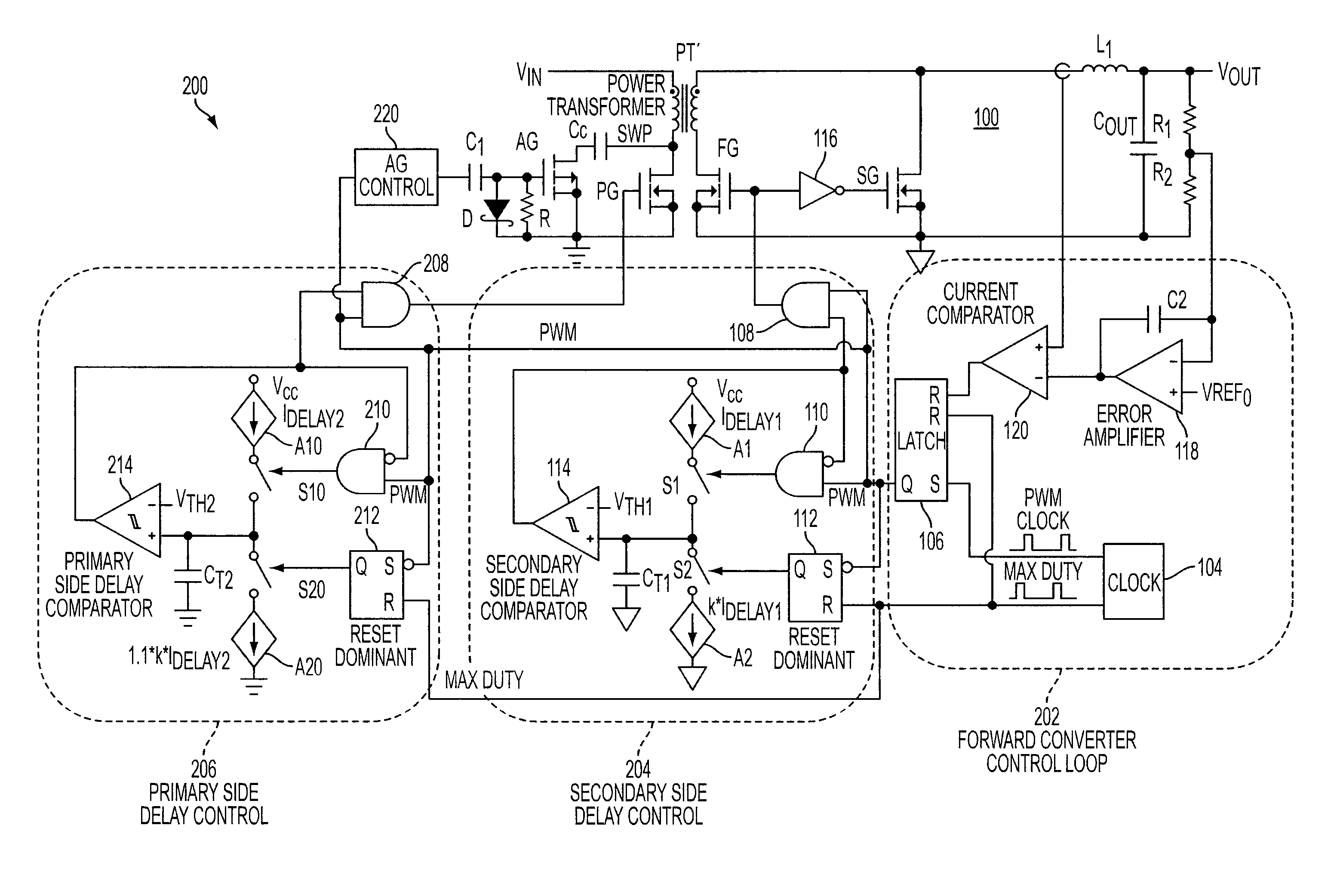
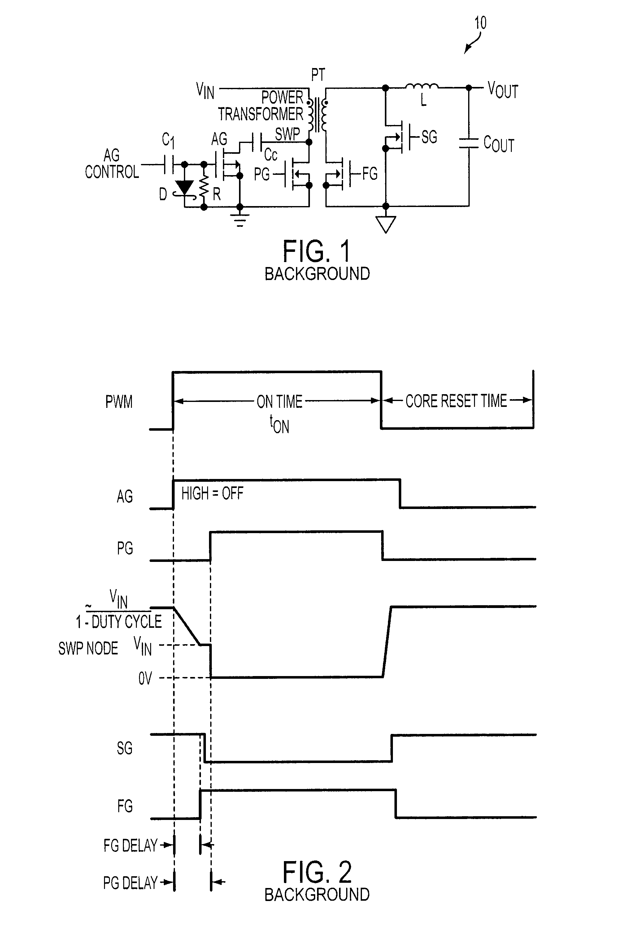
[0038]The present disclosure will be made using an example of a peak current mode control in a forward converter with active clamp reset. It will become apparent, however, that the concepts described herein are applicable to any method of controlling a forward converter with active clamp reset.

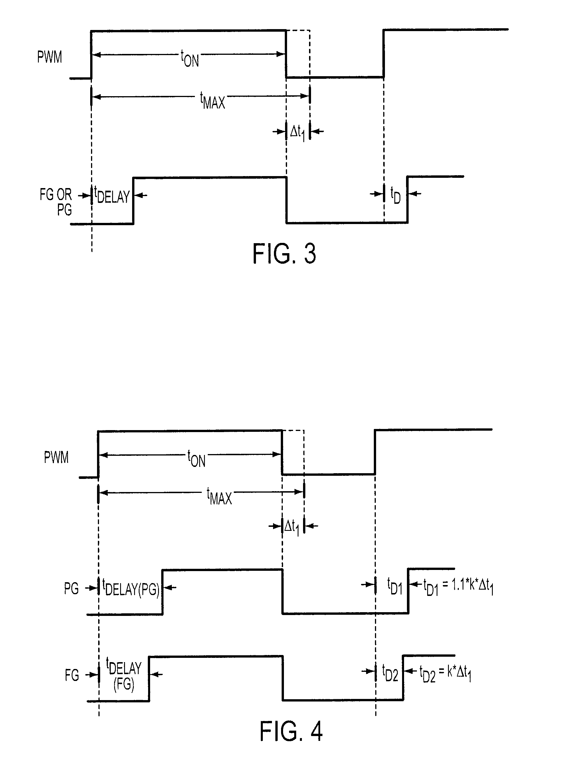
[0039]FIG. 3 illustrates the concept of extending achievable duty cycle of a forward converter with active clamp reset in accordance with the present disclosure. The on-time tON in FIG. 3 indicates an actual on-time of a PWM control signal in a current cycle of the converter. The maximum on-time tMAX defines the maximum on-time value of the PWM control signal to provide sufficient core reset time to reset the transformer. Further, the user may program the respective delay time tDELAY that defines a delay from the time when the active clamp gate AG turns off to the time when the primary gate PG or the forward gate FG turns on.

[0040]As the on-time tON of the PWM control signal in a current switc...


PUM


Abstract

Novel system and methodology are provided for controlling a DC/DC forward converter having a transformer with primary and secondary windings, a reset switch, and a first switch coupled to the primary winding of the transformer. The control system involves a PWM control circuit responsive to an output signal of the converter for producing a PWM signal to control switching of the reset switch, and the first switch. A period of the PWM signal includes an on-time interval for enabling transfer of power via the transformer when the first switch is on, and a reset time interval for enabling reset of the transformer when the reset switch is on. A maximum value of the on-time interval is pre-set to provide sufficient time for the reset. The reset switch is turned off when the PWM signal goes from a first level to a second level. A first delay period is set between time when the reset switch turns off and time when the first switch turns on. A first delay control circuit is provided for reducing the first delay time when the on-time interval approaches the maximum value. Further, the converter may include a second switch coupled to the secondary winding of the transformer. A second delay period shorter than the first delay period may be set between time when the reset switch turns off and time when the second switch turns on. A second delay control circuit may be provided for reducing the second delay period when the on-time interval approaches the maximum value.

Description

[0001]This application claims priority of provisional U.S. patent application No. 61 / 243,233 filed on Sep. 17, 2009 and entitled “METHOD FOR EXTENDING ACHIEVABLE DUTY CYCLE RANGE IN DC / DC FORWARD CONVERTER WITH ACTIVE CLAMP RESET.”TECHNICAL FIELD[0002]This disclosure relates to power supply systems, and more particularly, to circuitry and methodology for controlling a DC / DC forward converter with active clamp reset.BACKGROUND ART[0003]A DC / DC forward converter uses transformer windings to provide voltage conversion and galvanic isolation for the load. Power converters based on a forward topology are generally more efficient than flyback converters. By contrast with a flyback converter that stores energy as a magnetic field in the inductor when the switching element is conducting, a forward converter does not store energy in the transformer during the conduction time of the switching element. Instead, energy is passed to the output of the forward converter directly by transformer act...

Claims


Application Information

Patent Timeline
IPC IPC(8): H02J1/00H02M3/335
CPCH02M3/33538Y02B70/1475H02M3/33592Y02B70/10
Inventor COLEY, WILLIAM HALLHAWKES, CHARLES EDWARD
Owner ANALOG DEVICES INT UNLTD
Why Eureka
Try Eureka