Support structure for a plurality of lenses, lens, lens system, and optical system

a technology of supporting structure and lens, applied in the field of supporting structure for a plurality of lenses, can solve the problems of increasing the cost of producing a lens array, affecting the optical performance of the array, and not being used very well for the production of large and flat components, etc., and achieves the effect of increasing production costs and fast and cost-effective insertion

Inactive Publication Date: 2011-03-17
GLP GERMAN LIGHT PRODS
View PDF13 Cites 47 Cited by
  • Summary
  • Abstract
  • Description
  • Claims
  • Application Information

AI Technical Summary

Benefits of technology

[0021]According to a further embodiment of the present invention, the optical system can comprise a further lens group apart from a reflector, such as the TIR reflector, the ellipsoid of rotation, the CPC element or an aspheric lens. This lens group can be arranged, for example, between the inventive lens system and the reflector or the above stated alternatives in the optical path of the optical system. A further lens group can further improve the light beam quality of the optical system.
[0023]The invention allows that the lenses, e.g., the plano-convex or biconvex lenses are positioned as densely as possible, which ensures homogenous appearance and a compact device.
[0038]The finding of fast and cost effective insertion underlying the invention is to injection-mold a peg to the lenses (with quasi hexagonal flange) at two opposing sides that is plugged through small openings in the support. The peg can be secured on the rear side by any method (resilient security ring, heat staking, ultrasound bonding). The two latter methods have the advantage that the process can run automatically and can also be monitored for quality automatically.
[0039]There are no running costs for consumables such as adhesive, and the finished device can be processed further immediately after the last welding process without having to wait for the adhesive to cure.
[0041]Due to the pins (pegs) the lenses can be positioned very easily during insertion without necessitating time and cost intensive adjustment.
[0043]It is another advantage that the individual components can be separated from each other easily during recycling and can then be separately supplied to recycling.

Problems solved by technology

A known approach for producing a lens array is to injection-mold a large lens array, which has, however, the following disadvantages:Significant tool costs, since the whole very large array is one lens and hence the complete injection-molding tool has to be polished according to optical standards.It is not possible to produce the complete array with maximum transmission, since PMMA (polymethyl methacrylate) cools down during the injection process, which results in streaks in the plastic having a very negative effect on the optical performance.PMMA is relatively dimensionally stable, however, it cannot be used very well for the production of large and flat components like respective high-performance plastics.The array can only be used for one type of device.
This would, however, have disadvantages, namely:The cost for producing a lens array could be increased since the adhesive causes expenses.The adhesive joint could develop cracks over time and even fall off after long operation due to the UV strain and the different coefficients of thermal expansion of the materials.
This, however, is in contrary to the request for a precisely positioned lens.The correct positioning of the lenses before the openings in the support would have to be ensured by an external tool by fixing during the adhesive process.Curing the adhesive is a significant time factor in mass production: applying adhesive—inserting the lenses—fixing—waiting until the adhesive has cured—further processing.
This can again result in increased production costs compared to production without using adhesives.

Method used


Image

  • Support structure for a plurality of lenses, lens, lens system, and optical system
  • Support structure for a plurality of lenses, lens, lens system, and optical system
  • Support structure for a plurality of lenses, lens, lens system, and optical system

Examples


Embodiment Construction

[0055]With respect to the following description of the embodiments of the present invention, it should be noted that the same reference numbers are used throughout the description in the different figures for functionally identical or equal or functionally equivalent elements or steps for simplification reasons.

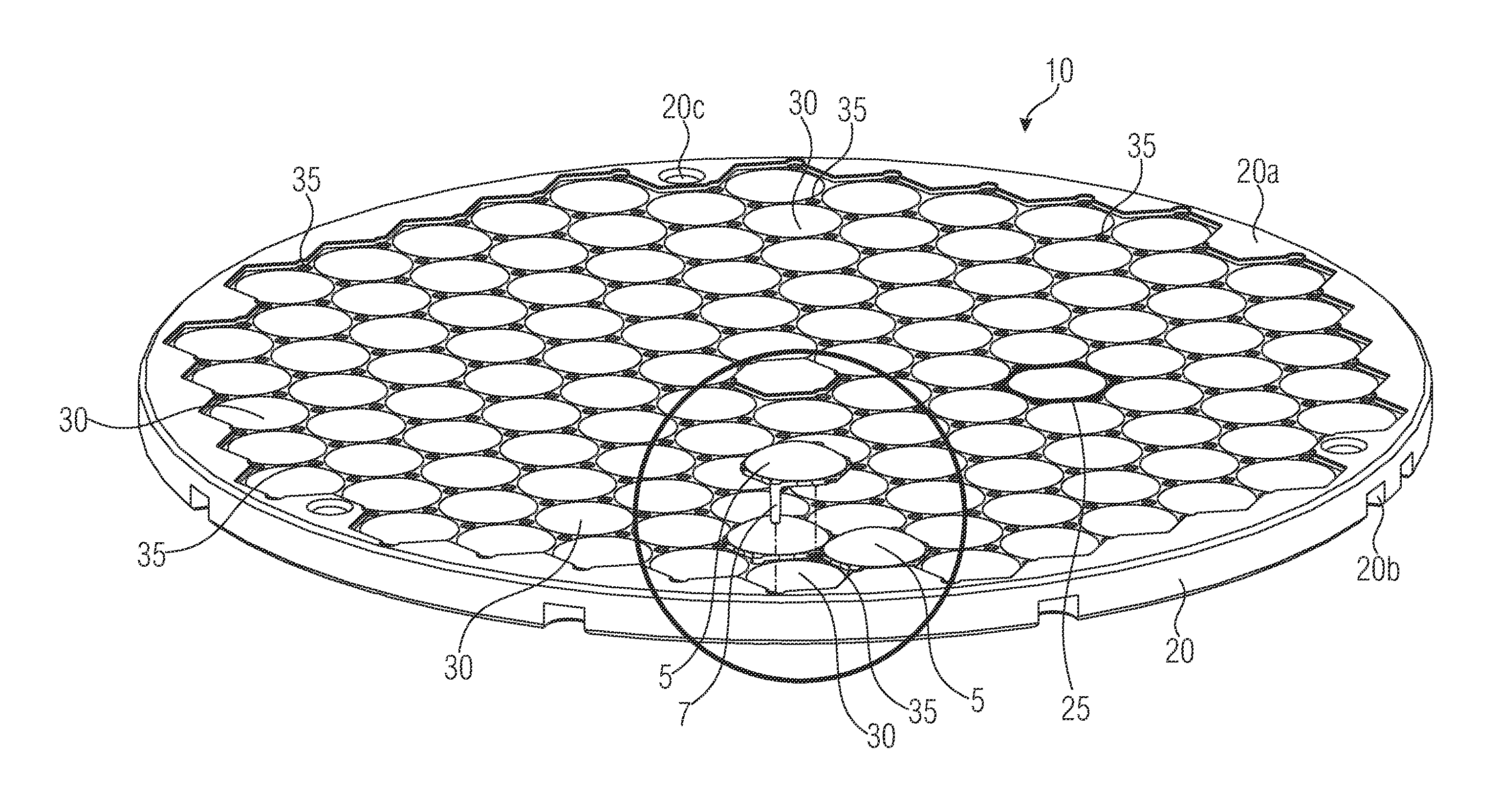
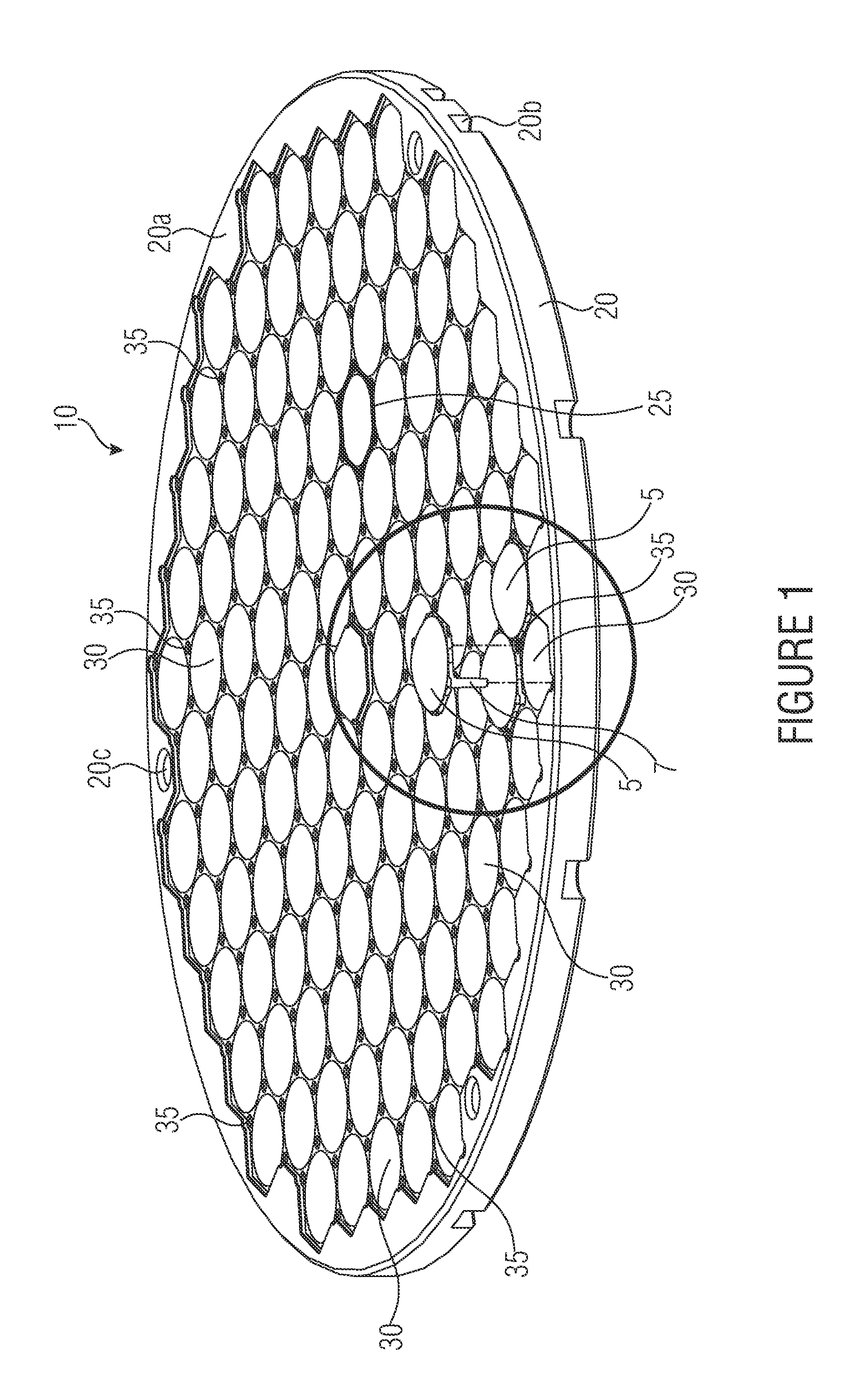
[0056]FIG. 1 illustrates in a perspective view a support structure or a support system 10 for a plurality of lenses 5 according to an embodiment of the present invention. The support structure 10 has a support plate 20 and a plurality of adjacent hexagonal portions 25 on the support plate 20. Each of the hexagonal portions 25 has a central opening 30. The hexagonal portions 25 form ridges that are formed in the shape of honeycombs. Each of the hexagonal portions has a central circular opening whose diameter can be larger than the width of the ridges of the hexagonal portions 25. The vertices or the corners of the adjacent hexagonal portions 25 can each have recesses 35. These...


PUM


Abstract

Embodiments show a support structure for a plurality of lenses having a support plate; and a plurality of adjacent hexagonal portions on the support plate, wherein a central opening penetrating the support plate is provided in each of the hexagonal portions, and wherein the support plate respectively comprises, at the vertices of the adjacent hexagonal portions, recesses for receiving a securing pin of a lens.

Description

CROSS-REFERENCE TO RELATED APPLICATIONS[0001]This application claims priority from European Patent Application No. 09011675.7, which was filed on Sep. 11, 2009, and is incorporated herein in its entirety by reference.BACKGROUND OF THE INVENTION[0002]The present invention relates to a support structure for a plurality of lenses, to a lens, to a lens system and to an optical system. In particular, the present invention relates to an optical system having a lens array with a plurality of light emitting diodes (LEDs) in red green blue (RGB) mixture, a total internal reflector (TIR) and a support with lenses, such as plano-convex lenses enabling a zoom function of the light beam by forward and backward motion. The optical system can, for example, be a spotlight or so-called moving head as they are used, for example, for illumination in stage technique or in events of all different types.[0003]A known approach for producing a lens array is to injection-mold a large lens array, which has, ...

Claims


Application Information

Patent Timeline
Patent Type & Authority Applications(United States)
IPC IPC(8): F21V7/00G02B7/02
CPCF21S2/005G02B27/0961F21V5/04F21V7/0091F21V13/02F21V13/04F21V14/02F21V14/06F21V17/101F21V17/164F21W2131/406F21Y2101/02F21Y2105/001F21Y2113/005G02B3/0056G02B7/021G02B7/10F21V5/007F21Y2105/10F21Y2115/10F21Y2113/13
Inventor SALM, MARKUS
Owner GLP GERMAN LIGHT PRODS
Why Eureka
Try Eureka