Microcalorimetry for x-ray spectroscopy

a microcalorimetry and x-ray spectroscopy technology, applied in the system field, to achieve the effect of high-resolution mapping

Active Publication Date: 2011-03-17
FEI CO
View PDF10 Cites 53 Cited by
  • Summary
  • Abstract
  • Description
  • Claims
  • Application Information

AI Technical Summary

Benefits of technology

[0018]An object of the invention, therefore, is to provide an EDS microcal

Problems solved by technology

Some embodiments use rapid electron beam scanning and periodic plasma cleaning to enable drift correction, and minimization of sam

Method used


Image

  • Microcalorimetry for x-ray spectroscopy
  • Microcalorimetry for x-ray spectroscopy
  • Microcalorimetry for x-ray spectroscopy

Examples


Embodiment Construction

[0034]Preferred embodiments of the present invention provide an improved microcalorimeter-type EDS system. Various embodiments of the system provide improved throughput, reliability, stability, and energy resolution.

[0035]A preferred method or apparatus of the present invention has many novel aspects, and because the invention can be embodied in different methods or apparatuses for different purposes, not every aspect need be present in every embodiment. Many the aspects of the described embodiments may be separately patentable.

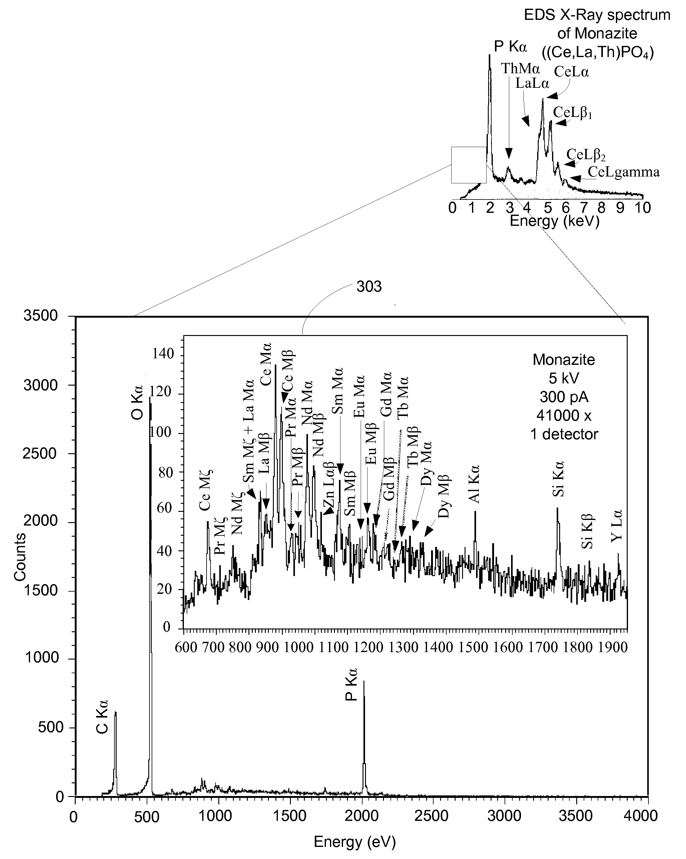
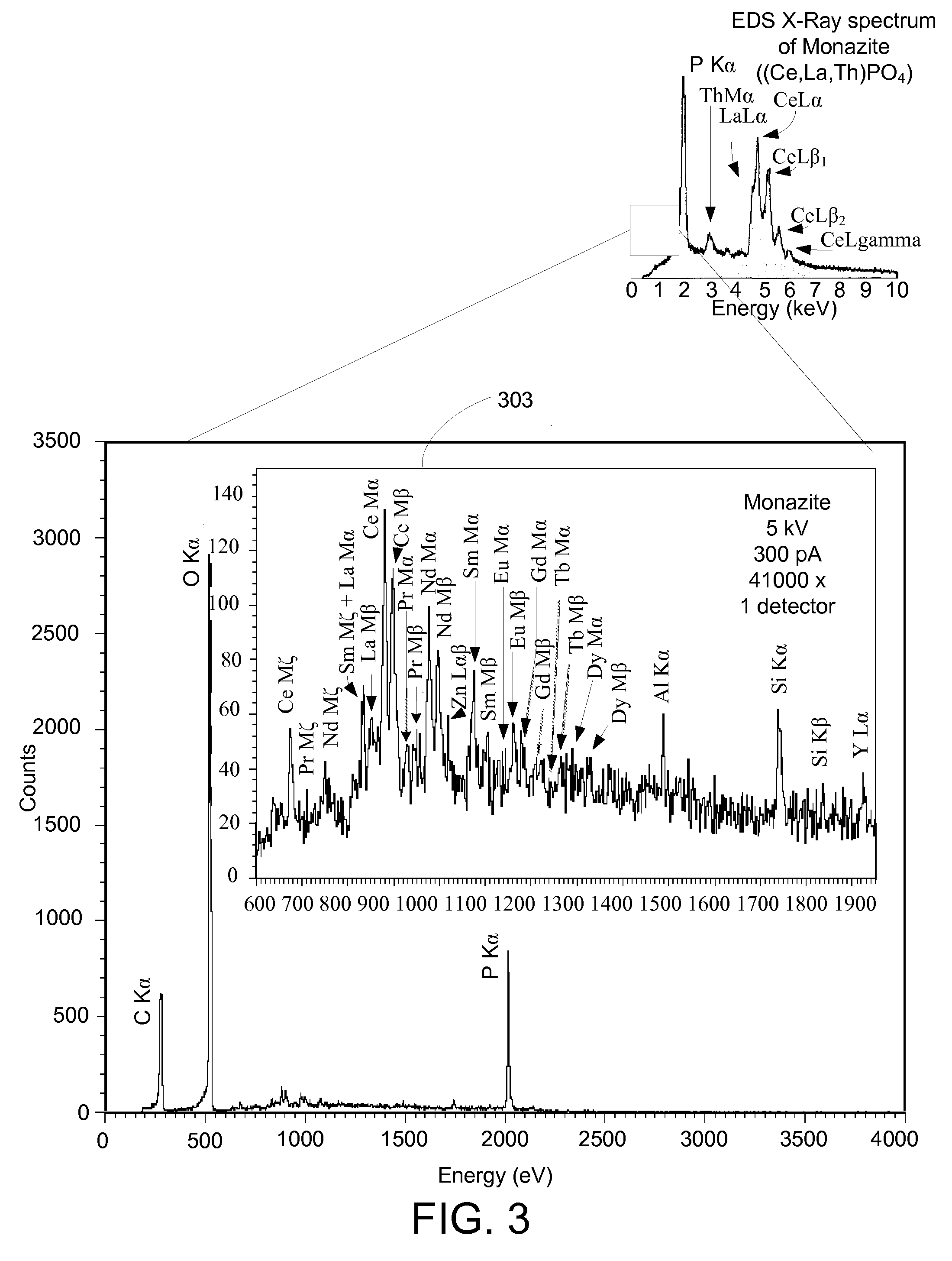
[0036]A preferred embodiment of the invention comprises an x-ray microcalorimeter together with a dual beam system configured so as to enable high-resolution two-dimensional or three-dimensional x-ray mapping. FIG. 4 shows a preferred embodiment of the present invention. A microcalorimeter-type EDS system 400 includes a vacuum chamber 401 for maintaining a sample 402 on a sample XYZ stage 403, electron beam column 404 and an ion beam column 405. Electron beam...


PUM


Abstract

An improved microcalorimeter-type energy dispersive x-ray spectrometer provides sufficient energy resolution and throughput for practical high spatial resolution x-ray mapping of a sample at low electron beam energies. When used with a dual beam system that provides the capability to etch a layer from the sample, the system can be used for three-dimensional x-ray mapping. A preferred system uses an x-ray optic having a wide-angle opening to increase the fraction of x-rays leaving the sample that impinge on the detector and multiple detectors to avoid pulse pile up.

Description

[0001]This application claims priority from U.S. Prov. Pat. App. No. 61 / 232,779, filed Aug. 10, 2009, which is hereby incorporated by reference.TECHNICAL FIELD OF THE INVENTION[0002]The present invention relates to a system for determining the composition of a sample.BACKGROUND OF THE INVENTION[0003]Electron probe microanalyzers and electron microscopes having an attached x-ray spectrometer are used to determine the composition of microscopic or nanoscopic regions of a surface. The detectors determine the energy or wavelengths of x-rays emitted from the sample and infer the composition of material under the electron beam from the energy or wavelength of the x-rays. Because the x-rays characteristic of different materials may have energies that are only slightly different, a detector needs sufficient resolution to differentiate between closely spaced x-ray energies. To process a sample in reasonable amount of time, x-ray detectors need to be able to process a large number of x-rays e...

Claims


Application Information

Patent Timeline
IPC IPC(8): G01N23/083
CPCG01N23/20033H01J2237/2442H01J37/256H01J37/244
Inventor TOTH, MILOSSCHEINFEIN, MICHAEL R.SILVER, ERICNARUM, DAVID
Owner FEI CO
Why Eureka
Try Eureka