Swept fiber laser source for optical coherence tomography

a fiber optic laser and optical coherence tomography technology, applied in the direction of laser details, wave amplification devices, electrical devices, etc., can solve the problems of limited depth penetration beyond the retinal pigment epithelium (rpe), water absorption, and other issues, to achieve the effect of low threshold pump power, large tuning range, and easy to reach deep saturation

Inactive Publication Date: 2011-03-24
MULTIWAVE PHOTONICS
View PDF5 Cites 13 Cited by
  • Summary
  • Abstract
  • Description
  • Claims
  • Application Information

AI Technical Summary

Benefits of technology

[0010]Compared with laser ring cavity lasers, linear cavity lasers have the advantage that the gain medium amplifies the laser light twice per circulation, thus making it easy to reach deep saturation. Therefore, large tuning ranges as well as a low threshold pump power and high slope efficiency can be easily achieved.

Problems solved by technology

Although the majority of retina imaging reports refer to this band, and ultrahigh resolution has also been demonstrated in this wavelength region for resolving intra-retinal layers, it has limited depth penetration beyond retinal pigment epithelium (RPE).
Water absorption, on the other hand, represents a more critical limitation especially when imaging a biological sample because of its high content (˜90%) of water.
The OCT systems that use 1050 nm broadband light sources need an expensive InGaAs linear camera for photodetection, which greatly increases the overall cost of the unit.

Method used


Image

  • Swept fiber laser source for optical coherence tomography
  • Swept fiber laser source for optical coherence tomography
  • Swept fiber laser source for optical coherence tomography

Examples


Embodiment Construction

[0020]Further features and advantages of the invention, as well as the structure and operation of various embodiments of the invention, are described in detail below with reference to the accompanying FIGS. 1-7, wherein like reference numerals refer to like elements. Although the fiber source is described in the context of optical coherence tomography, one of ordinary skill in the art readily appreciates that the present invention can be implemented in any type of system where it is desired to implement a swept fiber laser source with a wavelength emission centered near 1060 nm, for example, optical sensing (strain and temperature).

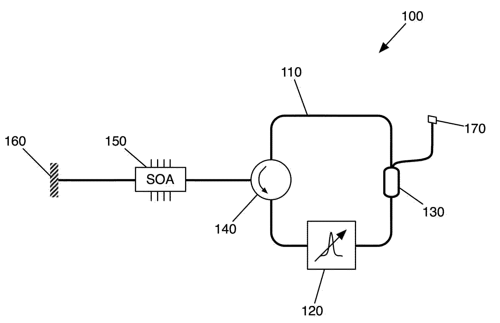
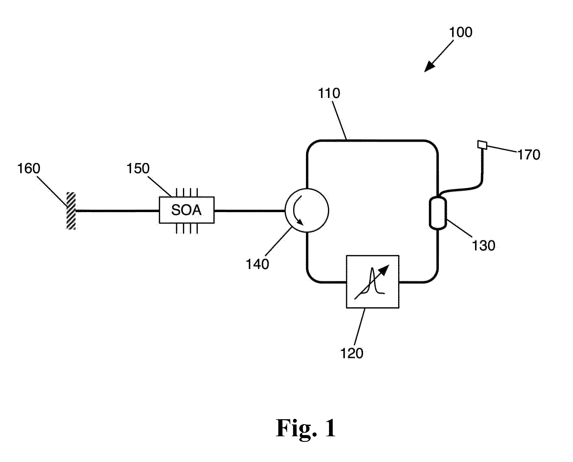
[0021]FIG. 1 illustrates a swept fiber laser source 100 according to an embodiment of the invention. The swept fiber laser source 100 comprises a semiconductor optical amplifier (SOA) device 150 spliced at one fiber end to a common-port of a polarization-maintaining (PM) optical circulator 140. The other fiber end of the SOA device 150 is spliced to a PM ...


PUM


Abstract

The present invention provides a swept fiber optic laser source for optical coherence tomography emitting around ˜1060 nm wavelength, with tuning range higher than 50 nm, sweep repetition rate from DC to 40 kHz, instantaneous linewidth shorter than 50 pm (FWHM), and providing an average output around 1 mW (or 20 mW with output optical booster amplifier). The fiber laser source is based on a proper linear-cavity fiber laser configuration, with an intra-cavity half-symmetrical confocal Fabry-Perot tunable fiber (FP-TFF) filter and semiconductor optical amplifier (SOA), a device combination that gives a very robust and vibration-resistant laser configuration.

Description

BACKGROUND OF THE INVENTION[0001]1. Field of Invention[0002]This invention relates to optical coherence tomography and more specifically, to a swept fiber optic laser source centered near a wavelength of 1060 nm with a tuning range higher than 50 nm, a sweep repetition rate from DC to 40 kHz, an instantaneous line-width shorter than 40 pm (FWHM), and providing an average output power around 1 mW (or 20 mW with an output optical booster amplifier).[0003]2. Description of Related Art[0004]Commercially available retinal ophthalmic optical coherence tomography (OCT) systems operate at a central wavelength of approximately 820 nm due to the relatively low cumulated absorption of the eye tissue at this wavelength. Although the majority of retina imaging reports refer to this band, and ultrahigh resolution has also been demonstrated in this wavelength region for resolving intra-retinal layers, it has limited depth penetration beyond retinal pigment epithelium (RPE). For imaging features be...

Claims


Application Information

Patent Timeline
Patent Type & Authority Applications(United States)
IPC IPC(8): H01S3/30
CPCH01S3/06754H01S3/06791H01S3/09415H01S2301/02H01S3/1618H01S5/141H01S5/146H01S3/1062
Inventor LOBO RIBEIRO, ANTONIO B.TRIFANOV, IRINANEAGU, LIVIU
Owner MULTIWAVE PHOTONICS
Why Eureka
Try Eureka