Visual perception system and method for a humanoid robot

a humanoid robot and visual perception technology, applied in the field of humanoid robot control, can solve the problems of relative time consumption, added engineering, installation, and other expenses, and achieve the effect of optimizing the luminance dynamic range of sensors and preventing image feature data loss

a humanoid robot and visual perception technology, applied in the field of humanoid robot control, can solve the problems of relative time consumption, added engineering, installation, and other expenses, and achieve the effect of optimizing the luminance dynamic range of sensors and preventing image feature data loss

US20110071675A1Active Publication Date: 2011-03-24GM GLOBAL TECH OPERATIONS LLC

Image

  • Visual perception system and method for a humanoid robot
  • Visual perception system and method for a humanoid robot
  • Visual perception system and method for a humanoid robot

Examples


Embodiment Construction

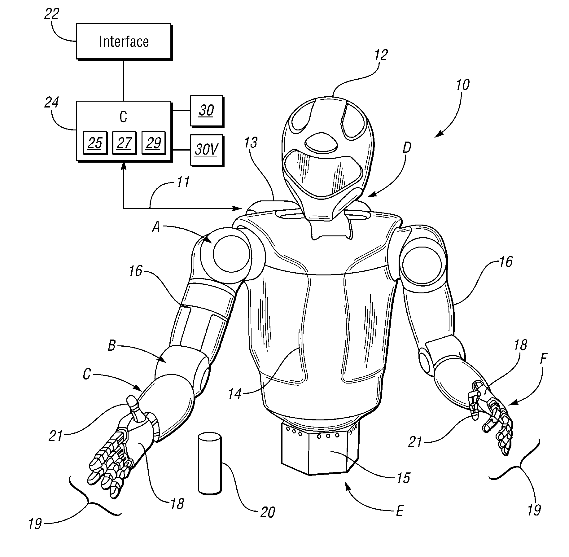
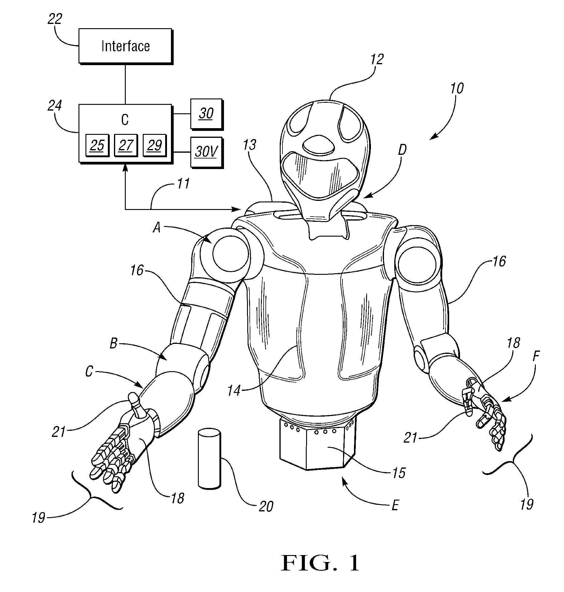
[0021]With reference to the drawings, wherein like reference numbers refer to the same or similar components throughout the several views, FIG. 1 shows a robotic system that includes a dexterous humanoid robot 10, which in turn is controlled via a distributed control system or controller (C) 24. The robot 10 is adapted to perform one or more automated or autonomous tasks with multiple degrees of freedom (DOF). According to one embodiment, the robot 10 is configured with a plurality of independently and interdependently-moveable robotic joints, such as but not limited to a shoulder joint, the position of which is generally indicated by arrow A, an elbow joint (arrow B), a wrist joint (arrow C), a neck joint (arrow D), and a waist joint (arrow E), as well as the various finger joints (arrow F) positioned between the phalanges of each robotic finger 19.

[0022]Each robotic joint may have one or more DOF. For example, certain joints such as the shoulder joint (arrow A), elbow joint (arrow...


PUM


Abstract

A robotic system includes a humanoid robot with robotic joints each moveable using an actuator(s), and a distributed controller for controlling the movement of each of the robotic joints. The controller includes a visual perception module (VPM) for visually identifying and tracking an object in the field of view of the robot under threshold lighting conditions. The VPM includes optical devices for collecting an image of the object, a positional extraction device, and a host machine having an algorithm for processing the image and positional information. The algorithm visually identifies and tracks the object, and automatically adapts an exposure time of the optical devices to prevent feature data loss of the image under the threshold lighting conditions. A method of identifying and tracking the object includes collecting the image, extracting positional information of the object, and automatically adapting the exposure time to thereby prevent feature data loss of the image.

Description

STATEMENT REGARDING FEDERALLY SPONSORED RESEARCH OR DEVELOPMENT[0001]This invention was made with government support under NASA Space Act Agreement number SAA-AT-07-003. The government may have certain rights in the invention.TECHNICAL FIELD[0002]The present invention relates to the control of a humanoid robot, and in particular to a system and a method for automatically finding, tracking, and measuring various features and / or objects in the field of view of the humanoid robot.BACKGROUND OF THE INVENTION[0003]Robots are automated or autonomous devices that are able to manipulate objects using a series of rigid links, which in turn are interconnected via articulations or motor-driven robotic joints. Each joint in a typical robot represents an independent control variable, also referred to as a degree of freedom (DOF). End-effectors are the particular links used for performing a task at hand, e.g., grasping a work tool or other object. Therefore, precise motion control of a robot may...

Claims


Application Information

Patent Timeline
24 Mar 2011
Publication
US20110071675A1
IPC
B25J9/06; B25J17/00; B25J19/04; G06K9/00
CPC
G06K9/3216; H04N5/247; H04N5/332; H04N13/0203; G06T2207/20081; G06T2207/10016; G06T2207/10028; G06T2207/10048
Inventors
WELLS, JAMES W.; MC KAY, NEIL DAVID